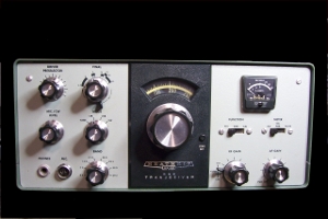
Restoring The Heathkit HW-101
Amateur Radio SSB Transceiver
![]()
![]()
Click Any Picture For Larger
View
I acquired this HW-101 after the death of a family
member. It had been sitting in the closet for a number of years, and
having finished up several other projects and looking for something to
do, I decided to take on the task of restoring this unit and putting it
back on the air.
The HW-101 born was out
of three previous models, the SB-100, SB-102, and the HW-100. Like the
previous models, it covered the 80 through 10 meter amateur radio bands
on Single Side Band or CW at 100 watts, and was one of the most popular
of Heathkit's ham radio products. It was a dependable and well designed
radio that was sold in kit form for $399. It was often a ham radio
operator's first introduction to Single Side Band (SSB) mode of
communications. Even at a cost of $399.95, it was quite a bit more
afforadable than other factory built transceivers that were currently
on the market. The Collins KWM-2, one of the most popular ham radio
transceivers ever, cost $1,250 in 1959. The HW-101 was released in time
for the Christmas market in 1970 and was in production for thirteen
years. Although actual production figures are sketchy, it is estimated
that Heath sold between 30,000 and 40,000 of these units.
SPECIFICATIONS
Receiver
Transmitter
|
|
|
|
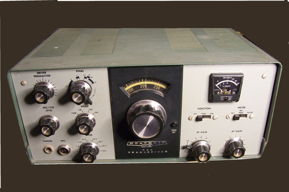
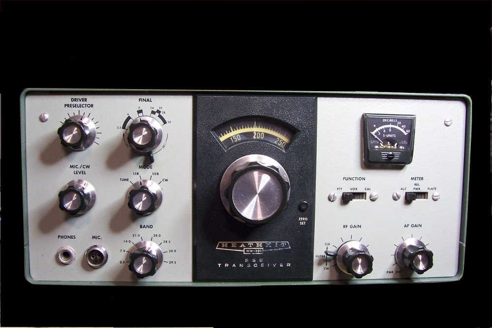
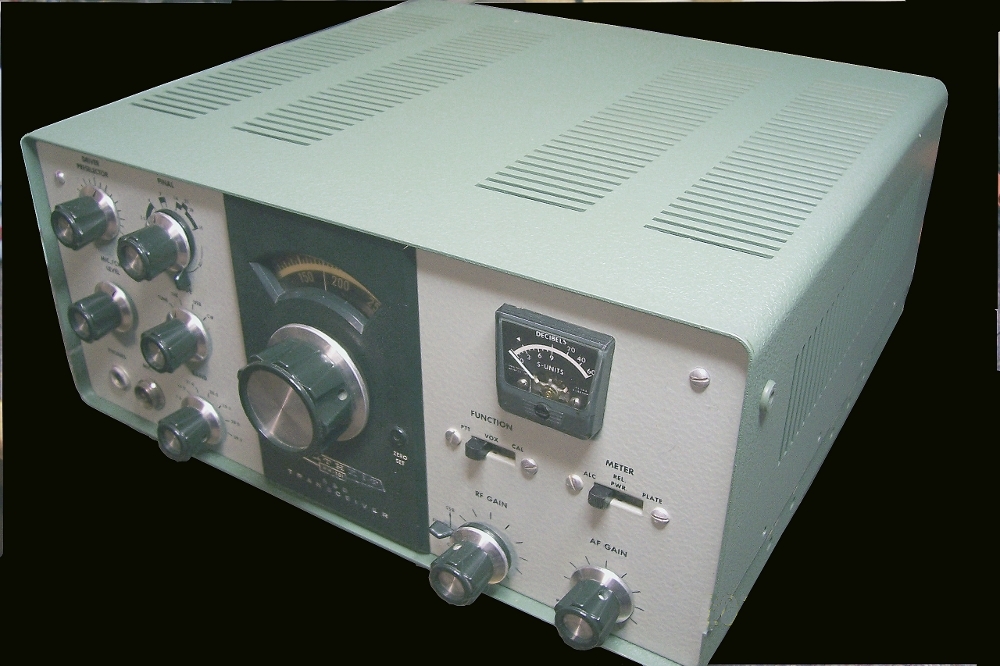
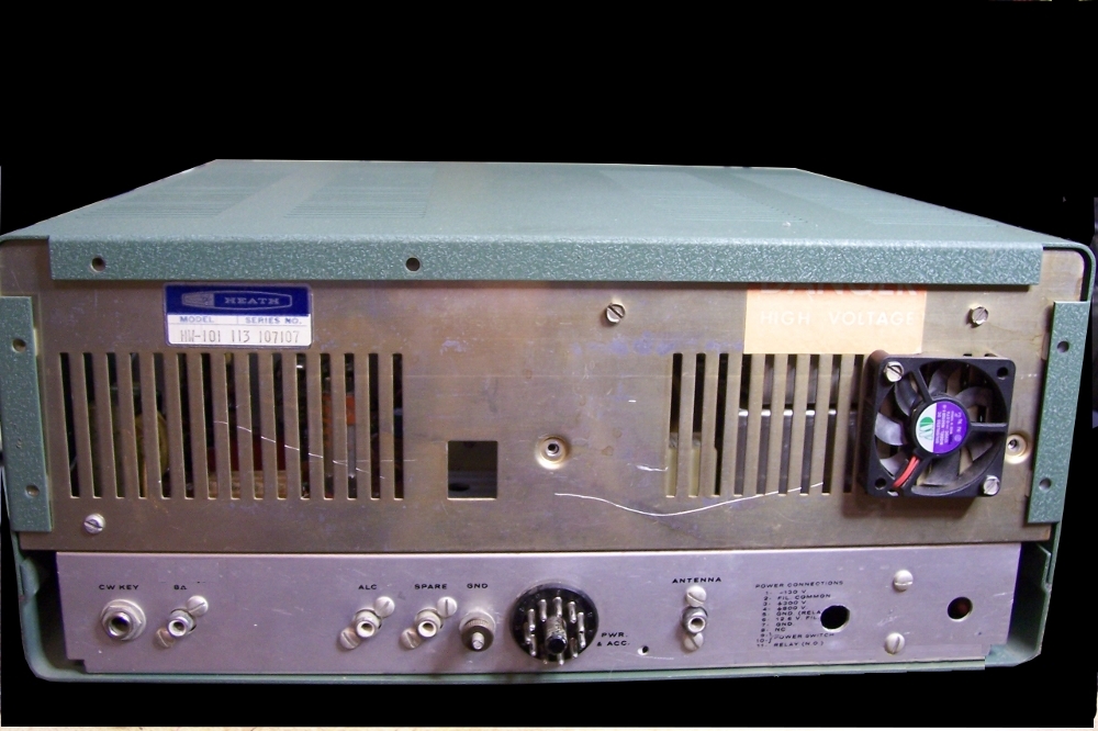
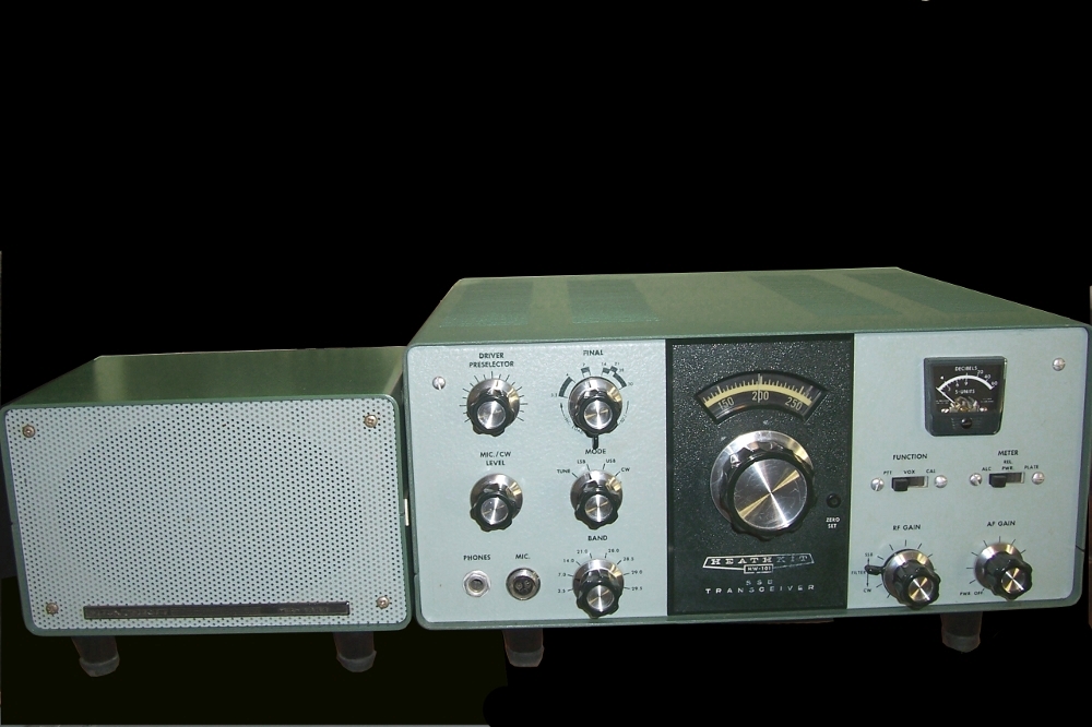
The condition of the unit wasn't too bad. The paint on the cabinet was in fair condition with scratches, and some fading as can be seen in the photos. The front panel, with exception of some wear on the Heathkit logo, was in very good condition. |
 |
|
|
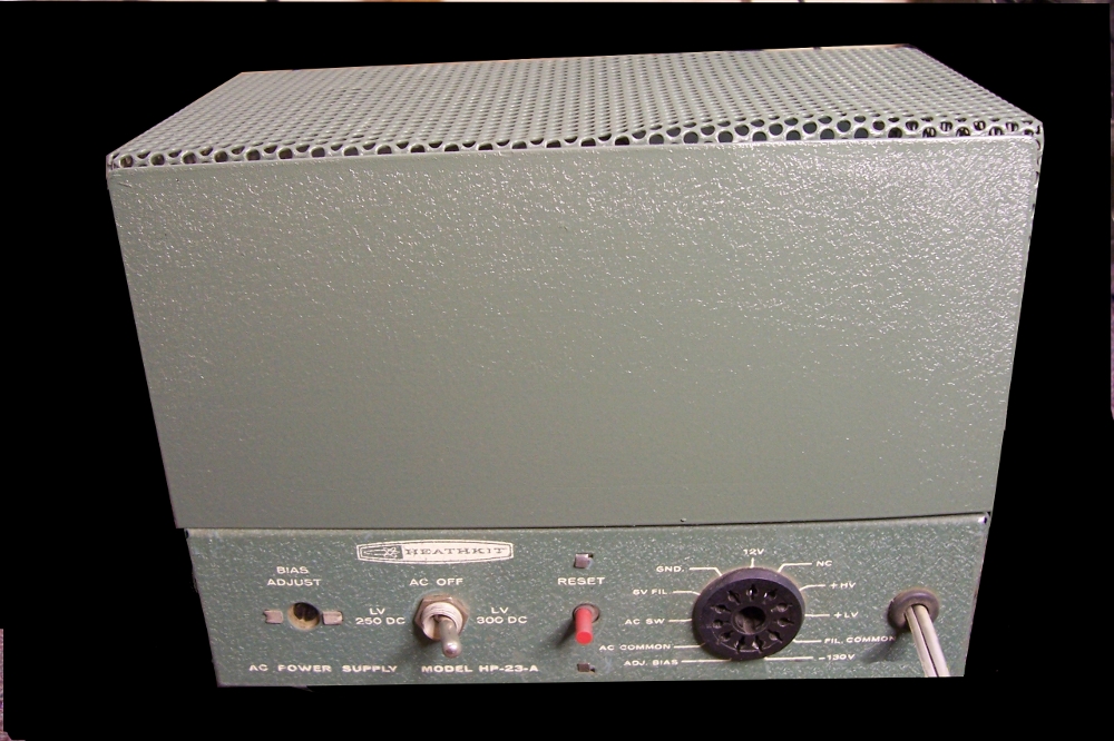
I used the variac to bring power up slowly on the separate HP-23 power supply. The voltages all came up to specs so I connected it to the transceiver and powered it up. The receive made noise and connecting an antenna, a number of stations were tuned in on the 40 meter band. So at least I knew I was starting out with a working unit. |
|||||||||||||||||||||||||||||||||||||||||||||||||
|
|
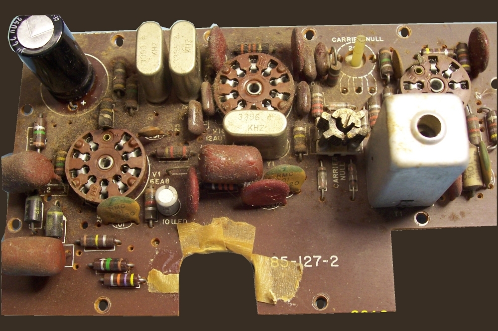
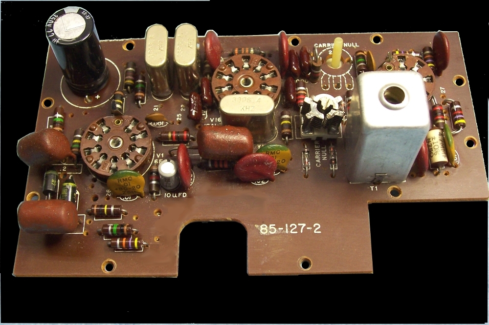
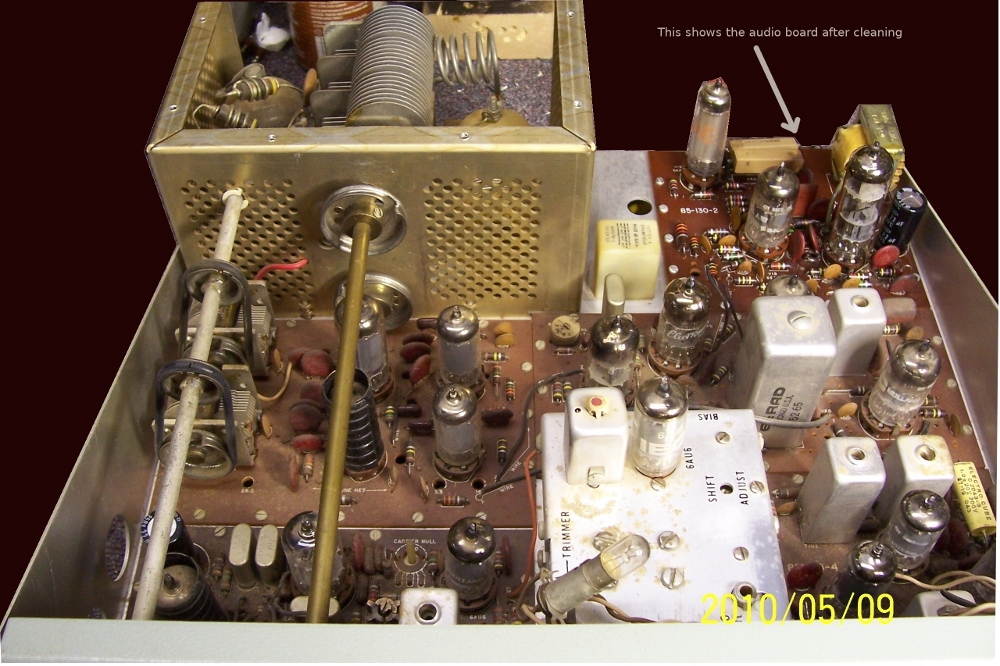
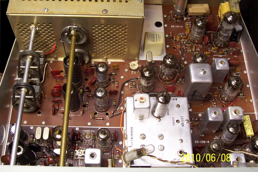
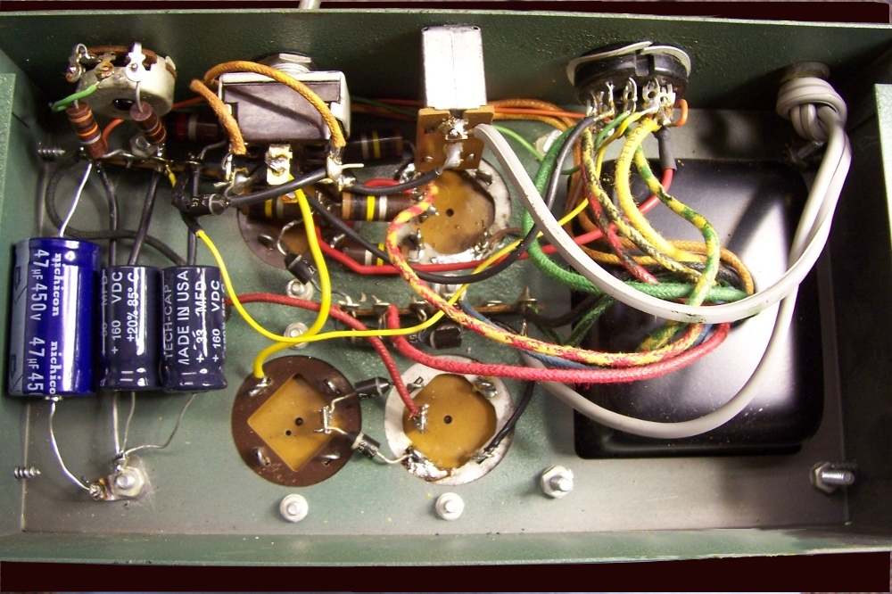
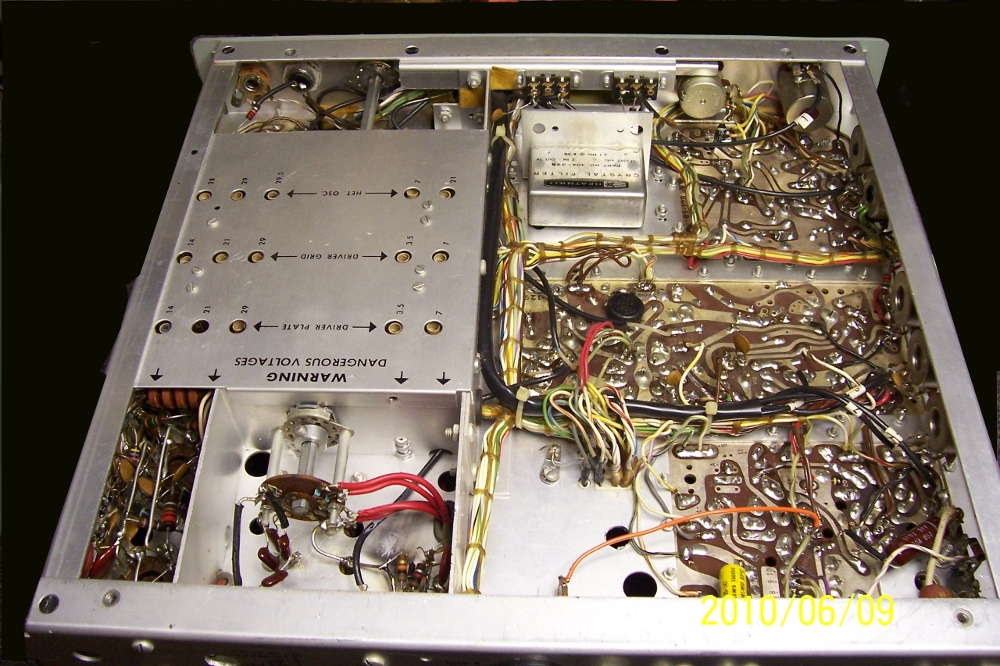
The circuit boards were covered with a layer of dust and grime so I started there first. Each board was removed one at a time and cleaned using a solution of Simple Green and water, then rinsing with plain water and drying with a heat gun. After cleaning, each board was re-installed and the united tested to make sure everything had been correctly re-connected. There are a number of wires that must be disconected from each board for removal. All electrolytic capacitors were replaced. The pictures show the before and after. |
|||||||||||||||||||||||||||||||||||||||||||||||||
>
 |
|
|
With all the newly cleaned circuit boards installed, the transceiver was again powered up for a final check that everything was still working. The dial tuning mechanism was removed, cleaned and re-lubed. The next task was to do a complete alignment of the circuits and neturalization of the 6146 final tubes, however I decided to turn my attention to the HP-23 power supply and replace the electrolytic capacitors before continuing with the transceiver alignment. | |||||||||||||||||||||||||||||||||||||||||||||||||
|
|
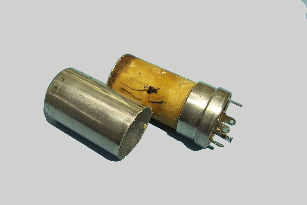
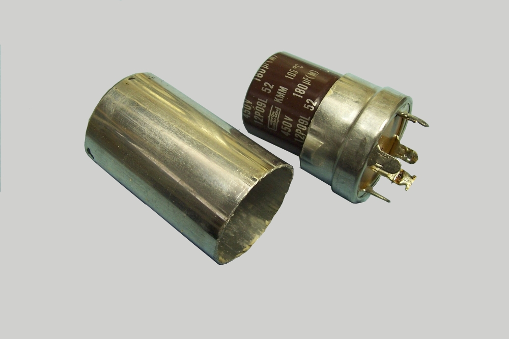
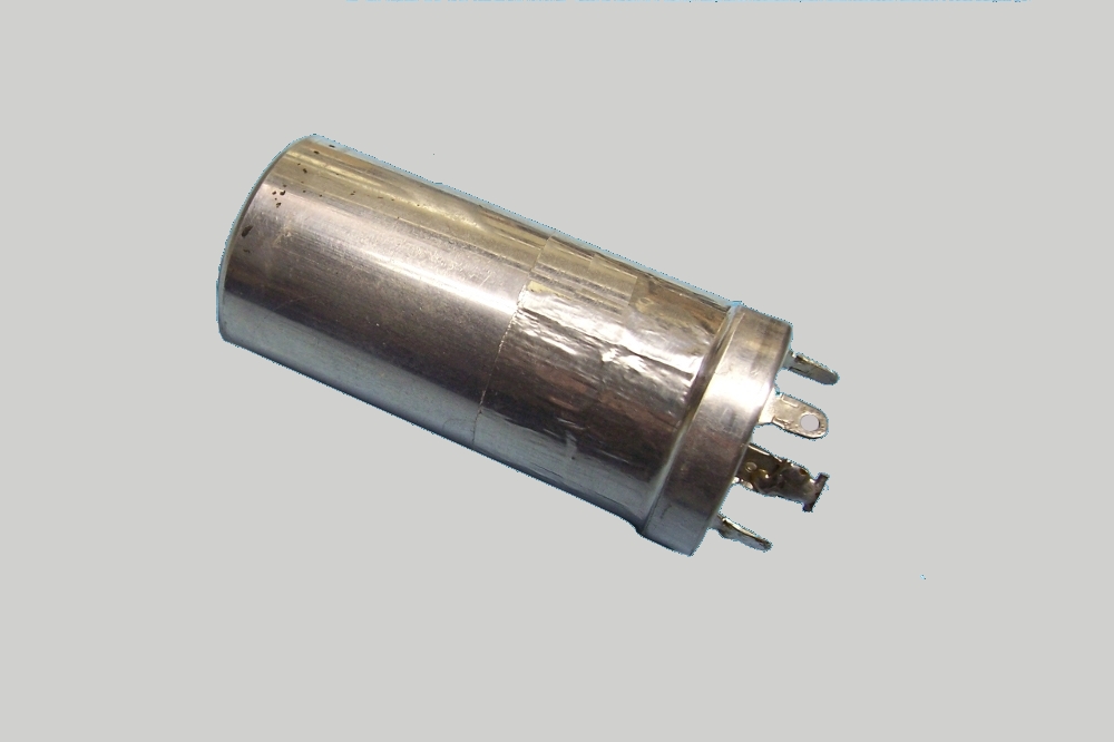
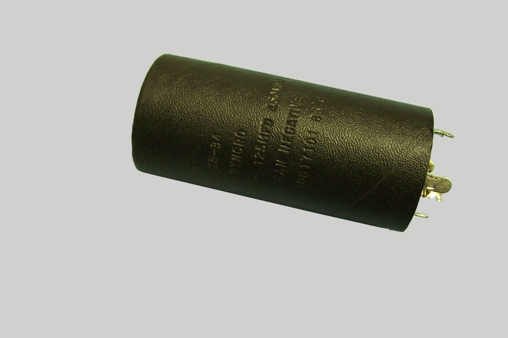
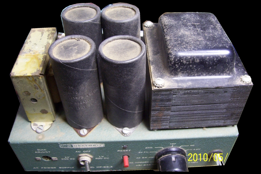
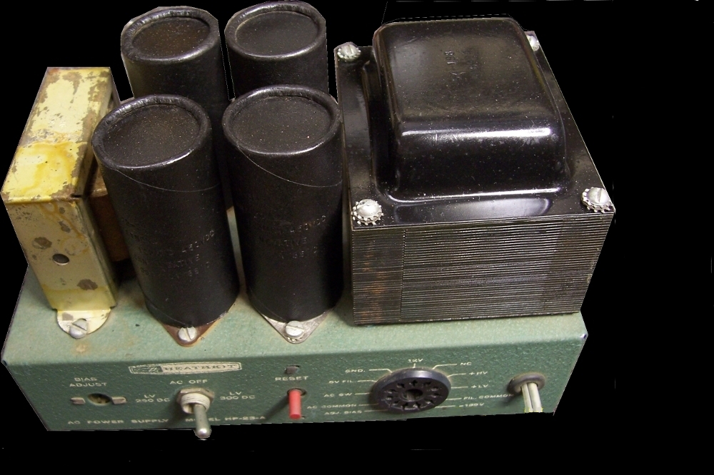
After the four high voltage capacitors were removed from the power supply the cardboard sleeves were removed and a Dremel tool, with a cutting wheel, was used to cut the cans just above the bottom. After the old capacitor was removed, holes were drilled through the base next to the lugs to accept the leads of the new capacitor. New 180 mdf 450 volt capacitors were installed, the leads soldered to the lugs on the base. The can was then inserted over the new capacitor and held in place with aluminium tape. The cardboard sleeves and the power transformer cover were given a coat of black paint and the tubes installed over the newly re-stuffed capacitors. |
|||||||||||||||||||||||||||||||||||||||||||||||||
 |
 |
|
|
With the power supply recapped, it was back to the transceiver for testing and alignment. Before starting the restoration process, a copy of the manual was obtained from the Internet. The alignment and neuturalization of the final tubes is pretty straight forward and can easily be done without any special equipment. After alignment the unit was connected to a 40 meter dipole antenna and tuning around the band found plenty of signals being received with good clarity. The receiver has good sensitivity, and pulls out the weak signals well. In comparing it to my Collins KWM-2, and a Drake 2B, I would say it is every bit as good on receive. The transmitter was loaded into a dummy load and an external watt meter showed 100 watts output, just as it should be. Several contacts were made on the air with good signal and audio reports. The only problem that has not yet been resolved is the stability in the VFO, which tends to jump frequency a bit from time to time even after a 20 minute warm up. I plan on removing the VFO unit and tuning mechanism once more to attempt to correct the problem. |
|||||||||||||||||||||||||||||||||||||||||||||||||
|
|
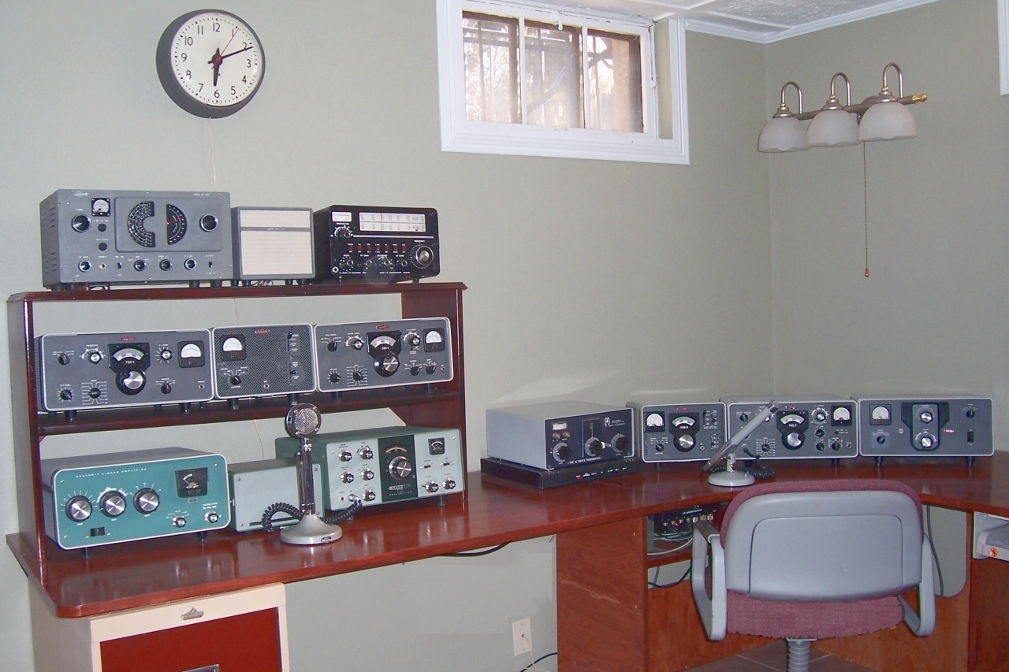
Next, attention was turned to the cabinet and the poor paint condition. The cover on the bottom of the HP-23 supply supply was in excellent condition, so I took it down to the local hardware store and had a quart color matched in eggshell enamel. The transceiver and power supply cabinet were spray painted and the results are excellent. I was also able to find a Heathkit HS-1661 matching speaker on the Internet and was also painted as it did not exactly match the Heathkit green of the transceiver. With twenty-one tubes, the unit can run rather hot, especially since the two 6146 final tubes give off quite a bit of heat, I attatched a small computer fan to the rear of the final cage to provide a bit of air flow. The fan is 12 volts dc so a diode and electrolytic cap was use to provide 6 volts dc from the 6 volt ac filament supply. The fan provides suficient air flow to keep things cooled down a bit even running on 6 volts. This modification can be seen in the picture of the rear of the unit below. Numerous contacts have been made on 40 meters with good signal and audio quality reports. My first serious amateur radio rig was the Heathkit SB-102 transceiver, one of the predecessors and a more expensive version of the HW-101. The SB-102 had a more stable VFO, a better tuning mechanism and other improvements over the 101. Restoring the HW-101 was a trip down memory lane, and it will make a good back up unit for the station. |
|||||||||||||||||||||||||||||||||||||||||||||||||
 |
 |
I welcome your comments, if you have a moment
please read/sign the guest book.
| |
