Airline TRF Cathedral - Chassis 326W
 |
|
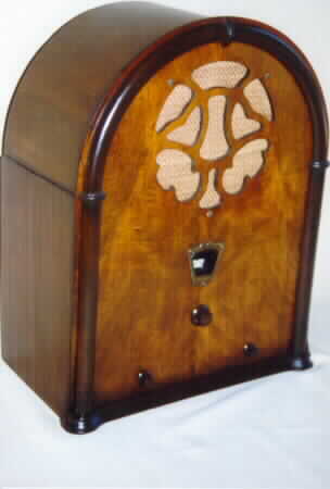
The cabinet was completely refinished. The old finish was removed using lacquer thinner. The lower side panels were missing quite a bit of veneer so the old veneer was removed and new veneer applied. The new finish was applied using toning lacquers, the trim done in Van Dyke Brown, the rest in Cherry Brown, followed with several coats of clear lacquer. The grill cloth seen in the picture is temporary awaiting a more original reproduction type.
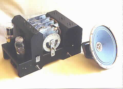 |
This is the restored chassis. The circuit design is five tube TRF circuit using 2 type 24's as RF amplifiers and a type 24 detector driving a type 45 output. The rectifier is a type 80. All capacitors were replaced, the insides of the ordinal capacitors were removed and new units installed inside the old containers. The tubes on the left in view are the 45 output and 80 rectifier. The three type 24's are enclosed in the shield next to these two tubes. The shield on the right side covers the power transformer, filter choke and filter caps. The large three section tuning capacitor can be seen between the two shields. The chassis and shields were repainted in the ordinal black color. The speaker field coil, which had to be rewound, is not used as a filter choke but is connected across the B+ voltage and is tapped to supply the screen voltage for the two RF amplifier tubes. Rewinding the field coil proved to be an interesting project.
A check with the ohm meter indicated no shorts on the B+ line so the chassis was plugged into the Variac and brought the voltage up slowly watching the amp meter. At 110 volts, the B+ measured up to specs, all tubes light up and AC input current draw is about .5 amp which is about right for the rated wattage of the set. An antenna was connected, but nothing from the speaker. A check with the signal tracer indicated signals getting all the way to the grid of the 45 output tube. Bringing the blade of a screwdriver near the pole piece of the speaker showed a lack of a magnetic field, indicating no current through the field coil. Rats!! A good bet the field coil is open.
Powering off the radio and a check with the ohmmeter confirmed that fear. I am hoping that perhaps a lead is broken at the connection of the coil wire and an external lead. After removing the coil from the speaker frame, The paper covering carefully unwrapped and it soon became obvious that many strands of wire are burnt into and repair of the coil is impossible.
Rewinding The Field Coil
According to the schematic, the total resistance of the field coil is 11,500 ohms, tapped at 2460 ohms for the screen voltage. An easy fix would be to substitute a 9.1K and 2.4K ohm resistor in place of the field coil to obtain the screen voltage, and use a PM speaker. However, I would like to maintain the originality of the set if possible. This means winding a new field coil. At a total resistance of nearly 12K ohms, that means a lot of wire.
I have several spools of magnet wire and a couple look to be about the same size as on the field coil. I don't know what gauge wire the coil is wound with so measuring a one foot length of wire from the coil comes out at slightly under 2 ohms. Measuring a one foot length from one of the spools reveals it to measure right at 2 ohms...close enough.
Let's see, 11,500 ohms at 2 ohm/ft., that would be almost 6000 ft. of wire tapped at 1,200 ft. for the screen voltage tap. The question now, is there enough wire on the spool to wind the coil? The number of feet is not indicated on the spool label. I weighed the field coil, then the spool of wire, and even allowing a few ounces for the spool itself, the spool of wire out weighs the field coil, so there should be enough.
Now I will finally get a chance to use that Morris Coil Winder I purchased some time ago. A new bobbin was constructed out of a thin cardboard tube and fitted to the coil winder. A jig was fashioned to hold and feed the spool of new wire. The winding begins. Since a tap at 2,400 ohms was needed I would occasionally stop and measure the resistance by scraping a small area of the enamel insulation so a reading could be taken. The exposed area was re-insulated by painting with a couple of coats of nail polish. The third try hit at just a little over 2,400 ohms, so couple of inches of wire were twisted and brought out for the tap. It took hundreds of hours of winding over two days to finally get to the required 11,500 ohms, and three nights for my right arm to stop going in circles when I sleep.
After wrapping a layer of heavy paper over the coil, the solder terminals were glued into place and the coil and external leads were soldered to the terminals and then a few of wraps of electrical tape finished it off. The coil would be across about 200 VDC in the set so I connected it to a 200 VDC source for testing. The current draw was just under .02 amps. The pole piece was inserted into the coil and the shank of a screwdriver confirmed a strong magnetic field. The coil and pole piece were next installed on the speaker. The cone was badly torn and very brittle and was beyond any repair. A re-cone was in order so a new cone was installed using the original voice coil and spider. The speaker was connected to the chassis, power applied and stations with plenty of volume appeared across the dial.
The Chassis
The two electrolytic filter cans were rebuilt, placing modern electrolytics inside the original cans, as was the rectangular can containing six bypass capacitors and the coupling cap from the plate of the 24 detector to the grid of the 45. The rust on the chassis was removed using Naval Jelly and steel wool. The chassis was then repainted in original black. The set has very good sensitivity and selectivity despite the rather simple TRF design.
 |