|
"How much?", I asked the dealer.As I am carrying it to my van I am thinking, " What am I doing with this thing? I'm a radio collector, I don't collect TV's--well, not usually. " I was wondering if there was the slightest chance of getting it to work. "No telling what is wrong with it , picture tube no good, bad fly-back transformer - just try to find one of those."
"Sixty-five", the reply.
"Take twenty-five?", I countered
"Take thirty-five", he countered my counter.
"Sold."
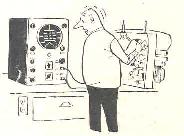
An advertisement for the set appeared in the December 1949 issue of Collier's magazine.
Trade Name: General Electric Model 10T1There are two solid state diodes; M4-1N64 video detector, and M5 -1N65 DC Restorer.
Manufacturer: General Electric Co., Electronics Dept., Electronics Park, Syracuse, New York
Type Set: Television Receiver
Tubes: Twenty
Picture: 10-inch - Black & White
Tuning Range: Channels 2 thru 13
Cabinet: Bakelite - Brown
Tube Line-up:
V1 6AU6.....1st RF Amp V11 6SQ7.....Audio Amp V2 6AG5.....2nd RF Amp V12 25L6......Audio Output V3 12AT7....Converter/Osc V13 6SL7......Sync Amp-Sync Sep V4 6AG5.....1st Video I-F V14 12SN7.....Vert Osc/Vert Sync V5 6AG5.....2nd Video I-F V15 6AL5......Horiz Sync Disc V6 6AG5.....3rd Video I-F V16 12SN7.....Horiz AFC/Horiz Osc V7 12AT7....1st/2nd Video Amp V17 19BG6.....Horiz Output V8 6AU6.....Sound I-F V18 25W4......Damper V9 6AU6.....FM Limiter V19 1B3.......HV Rectifier V10 6AL5.....Ratio Detector V20 10BP4.....Picture Tube
As I did not have the schematic diagram, I decided the first order of business was to get the Bakelite cabinet cleaned. Four screws on the bottom were removed and the chassis, along with the picture tube bezel, slid out of the cabinet. The knobs were removed along with the two screws that held the bezel to the front of the chassis, and the bezel removed. The cabinet and bezel were washed with water to remove the grime. A vigorous rub-down with Novus plastic polish brought the shine back to the Bakelite. A final polishing with brown wax shoe polish finished it off and made it look like new.
Click image for larger picture
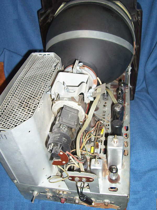
The chassis was very clean with almost no rust. The cabinet did not have any openings large enough to allow mice to get inside so there was no damage to wiring or components. A quick going over with the air compressor removed the layer of dust and a close inspection showed things to be in very good shape.
A trip to the Fort Worth public library yielded the schematic and alignment information from the Sam's PhotoFact folder 96-4. Armed with this I was ready to tackle the chassis.
After looking over the schematic I decided to bring up power using the Variac and check for any B+ voltages. The input voltage was brought up slowly while watching for any smoke or smells that would indicate trouble. The tube filaments began to glow, but the voltmeter showed no signs of B+. Power was removed and a quick check of the selenium rectifiers proved that they were defective as would be expected. These were replace with two 3 amp 600 piv diodes and power once again applied. The voltage-doubler circuit now produced the required B+ voltages and after tube warm-up a raster appeared on one-half of the picture tube.
The presents of a raster indicates that the horizontal oscillator, and fly-back transformer are working, and the picture tube has some life left. An antenna was hooked to the antenna terminals and the set tuned to one of the local channels. There was no sound from the speaker and no evidence of any picture on the raster. A quick check with a scope showed video signal coming out of the video I-F, confirming that the tuner and video circuits seem to be working. There is hope.
Since I intend to replace all capacitors, I decide to start with the electrolytics and then replace the paper caps in the vertical sweep generator section, since I suspect that is where the raster problem may be. Most of the electrolytics were tubular style mounted underneath the chassis and held in place with metal clips. After installing new caps, the set was powered up once again and all voltages checked OK. The caps in the vertical sweep generator were changed next, and upon power up, bingo!--full raster.
The next problem is to tackle the missing picture and sound. With the scope I could trace the video up to the input of V6, the 3rd video amplifier, but there is no signal on the output. The output of V6 feeds a detector circuit mounted in an I-F type can. A 1N64 diode is part of the detector circuit and the schematic shows the cathode tied to common. If this diode is shorted it will kill the video as well as the sound, as the sound signal is picked off at this point also. The diode is nowhere to be found. Could it be inside the can? The can was removed from the chassis and the insides taken out. There, mounted across one of the coils was the diode. I obviously did not have another 1N64, so I picked a small-signal diode from the diode drawer and soldered it in place of the 1N64. The can was replaced and the set powered up again. Double Bingo!! Picture and sound. Now we're getting somewhere.
Click image for larger picture
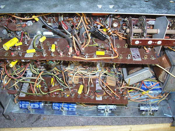
A decisions was made to go ahead and replace the remaining capacitors before proceeding with any more testing. This was quite a chore as there were a lot of capacitors and some were mounted on two vertical component boards as can be seen in the picture at left.
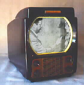
After capacitor replacement, the set was powered up and a set of rabbit-ears from a modern portable TV set were hooked to the antenna terminals. A quick check through the channels showed the set to be receiving signals on all of the local channels. The picture was fair, somewhat dim, probably due to the age of the picture tube. It did improve a little as the set warmed up. The sound was a somewhat fuzzy also. I suspected that an alignment might improve things. Proper alignment of a television set calls for a sweep generator. Not possessing one, I tweaked the various circuits, following the alignment chart, using the scope to monitor signals, watched the picture tube and listened for improvements. After tweaking, there was much improvement in both picture quality and sound. The next step is to borrow a sweep generator and do a proper job of alignment and maybe get even more improved performance.
Restoring the set was both fun and challenging. A friend who had seen the set, appeared one day holding a set of rabbit ears with a brown Bakelite base, obviously from the same era. He had found them in an antique shop and thought they would be just the thing to round out the restoration, and they do look perfectly at home on top of the set. Now if I could just talk one of the local VHF channels into re-running some of those early 50's shows like; Jackie Gleason, Jack Benny, Grand Old Opry, Dinah Shore, I Love Lucy, Your Show of Shows, to name a few, we would really be in business.
 I plan on borrowing a sweep generator and doing a proper alignment on the
set which should improve it's performance even more. I did build one of those
low power TV transmitter kits that takes the video and audio signals from a
VCR and transmits them on channel 3. The signal can be picked up on any TV
receiver several feet away. With this, I can put in a tape of some of the aforementioned programs and view them on the
GE set. Jackie Gleason just seems to be funnier when viewed on a TV of the era.
I plan on borrowing a sweep generator and doing a proper alignment on the
set which should improve it's performance even more. I did build one of those
low power TV transmitter kits that takes the video and audio signals from a
VCR and transmits them on channel 3. The signal can be picked up on any TV
receiver several feet away. With this, I can put in a tape of some of the aforementioned programs and view them on the
GE set. Jackie Gleason just seems to be funnier when viewed on a TV of the era.
 |