|  |
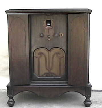
This little console, found in an antique mall in central Texas, is a Gulbransen brand, a trade name of Wells Gardner. It is a nine-tube TRF set using four type 26 RF amplifiers, one type 24 detector, one type 26 1st audio amplifier, two type 45 audio output and one type 80 rectifier. The power supply uses two filter chokes, one being the field coil of the speaker, and paper capacitors for filtering. Before high capacity electrolytic capacitors became available, filtering was accomplished using lots of inductance and paper capacitors in the range of 1-4 mfd.
Initial check out of the set revealed a shorted power transformer. This presented quite a problem as the transformer has five filament windings...two 2.5 volt, two 1.5 volt, and one 5 volt. There is nothing like that in new stock available. It seemed the only recourse was to rewind the transformer. I had never attempted this before so it was going to be a new experience.
Disconnecting the transformer was simple as all power leads terminate on a fiber board mounted on top of the transformer and simply removing a few nuts the board comes off leaving the transformer completely disconnected. The transformer was removed and disassembled and by counting the turns of the filament winding the turns-per-volt ratio could be determined. The 5 volt filament winding for the 80 rectifier had 20 turns which is a ratio of 4 turns-per-volt (20 turns / 5 volts = 4 turns-per-volt). The Morris Coil Winder was called into duty, I made a new cardboard bobbin and began. The first winding was the high-voltage winding. The schematic indicates the hv to be 300 volts each side of center-tap, so that would be 600 volts total which would be 2400 turns (600 volts × 4 turns-per-volt), tapped at 1200 turns for the center tap. Next came a layer of insulating (fish) paper, then the primary winding which would require 480 turns (120 × 4). Another layer of insulating paper then two of the filament winding (1.5v-6 turns and 2.5v-10 turns) were wound side-by-side, another layer of paper, two more side-by-side winding (1.5v and 2.5v), more paper and the last filament winding, the 5 volts for the 80, and a final layer of paper.
The transformer was reassembled and a line cord was connected to the primary and voltage was slowly brought up to 120 volts using the Variac...only a few mills current draw, looking good. The secondary voltages were measured and everything seemed OK. The leads were soldered to the terminal lugs, the fiber power connector board was installed and the set cautiously powered up, again using the Variac. After tube warm up the primary current draw settled in at about .5 amps, after some quick voltage checks the antenna lead was connected to the attic antenna. Since I did not have the speaker plugged in, (it was awaiting a new cone, a resistor was substituted for the field coil resistance) I used the signal tracer and traced signals all the way to the input of the first audio tube (type 26), but no output.
A quick check with the voltmeter indicates there is no voltage on the plate of the 26 tube. The plate voltage comes through the primary of the interstage audio transformer that drives the grids of the two push-pull 45's. Obviously the primary is open. Powering off and a quick check with the ohmmeter confirms that not only is the primary open, but the secondary as well. A new transformer is ordered along with some new 1.0 and 2.2 mfd Mylar caps that will replace the ones used as the filters in the power supply, all the other paper capacitors have been replaced. The chassis has been cleaned, some old wiring replaced, so as soon as the new parts arrive and installed, it should be up and running.
The interstage audio transformer and capacitors arrive and were installed. The set was powered up and B+ showed up to specs but upon tuning stations the sensitivity did not seem to be what I would expect. A little tweaking of the trimmer caps on the four-section tuning capacitor, helped some but not a lot. I decided to check the voltages on the tubes and found that the plate voltage on the 26's of the first two RF amp stages was only 60 volts, should be around 116 volts. I discovered a wire that was removed from a terminal where a bypass capacitor that had been rebuilt was attached and I had failed to hook the wire back up. This wire carries the B+ to the two 26's, so why was there any B+ there at all with this wire disconnected? The radio should not even be working.
The RF amplifier stages have compression trimmer neutralization capacitors from the plate of one stage to the plate circuit of the next. It turns out that one of these had become 'leaky' from general crud buildup and was providing a high resistance path to feed reduced B+ voltage to the plate circuit of these two tubes, enough to allow operation at reduced gain. The phenolic strip on which the trimmer capacitors were mounted was removed and all the capacitors were cleaned and reinstalled. Now there is no plate voltage on the two 26's until I re attached the B+ wire. With full plate voltage, there is plenty of gain and stations can be pulled in all over the band with plenty of volume. The selectivity of this set is very good for a TRF.
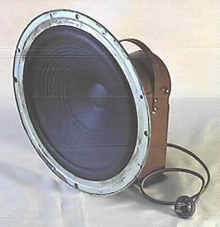
The new speaker cone arrived, the speaker was dissembled and everything cleaned and repainted then reassembled. The new cone was installed using the original voice-coil and spider. A new cord for the field coil and new wires going to the voice coil were installed. The field coil lead plugs into the rear of the chassis using a standard 110 vac type plug.
|
| |
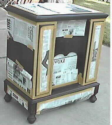
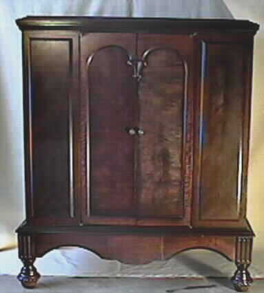
In the picture on the left the cabinet is been prepared for the application of toning lacquer and is being masked off to apply the Van Dyke Brown to the trim. At right, is the cabinet after the application of the toning lacquers. Medium Dark Walnut was used followed by several coats of clear lacquer.
| 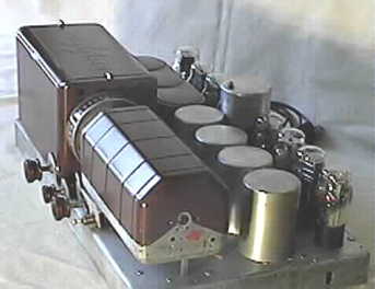 |
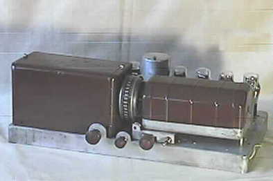
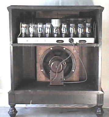
This shows the restored chassis. All capacitors were replaced. The old capacitors were removed from their containers and new Mylars installed inside. The cover over the power supply components can be see to the left and the cover over the 4 gang tuning capacitor on the right. The 4 aluminum cans cover the RF coils. In the picture to the right; at the center rear you can see an aluminum shield mounted on a stand-off that covers the top portion of the type 24 detector tube. The brown cover just behind the power supply compartment contains the interstage and output transformers, the covers have been repainted.
|
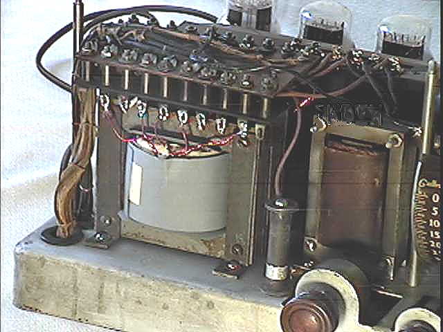
This photo gives a close-up view of the rewound power transformer. Just to the right of the transformer is the filter choke.
|
| 
|
 |