Restoring the Lafayette KT-200 Communications Receiver

|
The Lafayette KT-200 communications receiver was available either in kit form for $64.50, or wired and tested as the HE-10 for $79.95. The receiver was manufactured by Trio of Japan (Trio later became Kenwood) and was offered from 1959 to 1964. I purchased the unit in kit form in 1960 and it served as the receiver for my ham station when I acquired my Amateur Radio Operator's license in 1961. It was used in conjunction with a Heathkit DX-60 AM/CW transmitter. The receiver was also sold under the Trio brand as the 9R4J. In kit form, the band switch unit with coils came pre-wired and aligned so the construction consisted of assembling the components to the front panel, mounting the hardware to the chassis and wiring the power supply, IF strip and audio circuits.
The receiver did not have great selectivity so using it on the crowded Amateur Novice bands, where a Novice could only transmit using Morse code (CW), was somewhat of a challenge. The addition of a Heathkit Q-Multiplier helped quit a bit. Eventually I upgraded to a Hammarlund HQ-100 and being newly married, money in those days was not in abundance, so it was necessary to trade the KT-200 in towards the purchase price of the HQ-100.
|
A number of pieces of ham gear have come and gone over the years and I often wished I could have kept the little KT-200. I recently noticed that these units were appearing on ebay quite often and began to watch what they were selling for. One in like new condition with the original box sold for over $300! A bit pricey I thought. Finally another appeared that seemed to be going at a much more reasonable price as it was not in the best of condition, and from the sellers description one got the idea that the set did not work too well. I watched the bidding and sure enough it too went for more than I was willing to pay. The final price was about half of what the NIB unit sold for.
I continued to monitor the auction site and a short time later this second radio appeared up for auction again. This seller even used the same pictures and exact description as the first seller. I again assumed that the set didn't work very well and the current owner was disappointed with it. This time I was successful in bidding and obtained it for about half of what the second buyer gave for it.
Band Spread
Built-in "S" meter
Covers 550KC to 31MC In Four Bands
AVC - Variable BFO and RF Gain Controls
Switchable
Automatic Noise Limiter
Sensitivity is 3 microvolts (Signal to noise ratio is 20 DB at 3.5MC)
Selectivity is -60DB at 1MC
Image rejection is -40 DB at 3MC.
Not bad specs for a $65 all band receiver.
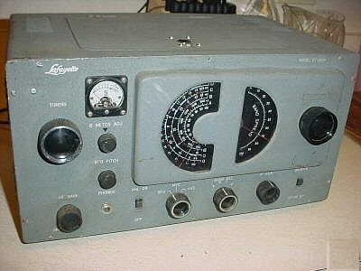
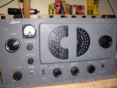
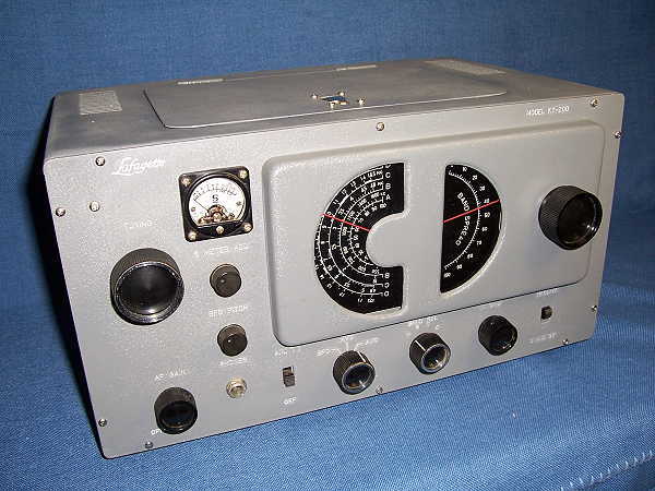
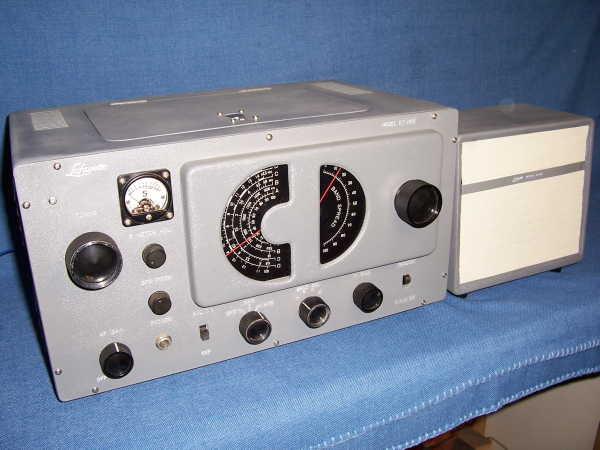
The receiver is styled somewhat after the Hallicrafters S-38 series of short wave receivers, as evident by the half-moon dials, however the set is a few steps up from the S-38.
Unlike the S-38 series, which incorporates an AC/DC type power supply and lacks an RF amplifier stage, the kt-200 set uses a transformer power supply. The circuit is superhetrodyne utilizing 8 miniature tubes; a 6DB6 as RF amp, 6BE6 oscillator, 6BE6 mixer, two 6BD6 IF amplifiers, 6AV6 for BFO and ANL, 6AV6 for detector/ first audio, 6AR5 for audio output, and 5Y3GT rectifier. An octal accessory socket is located on the rear panel. It also features weighted flywheel tuning for both main and bandspread tuning.
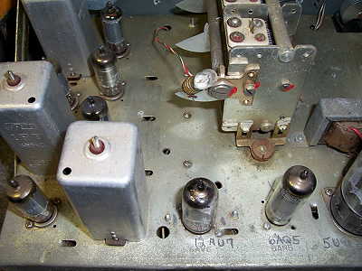
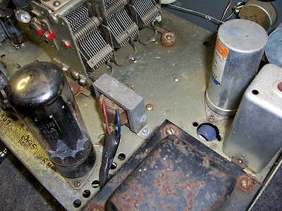
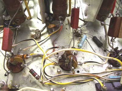
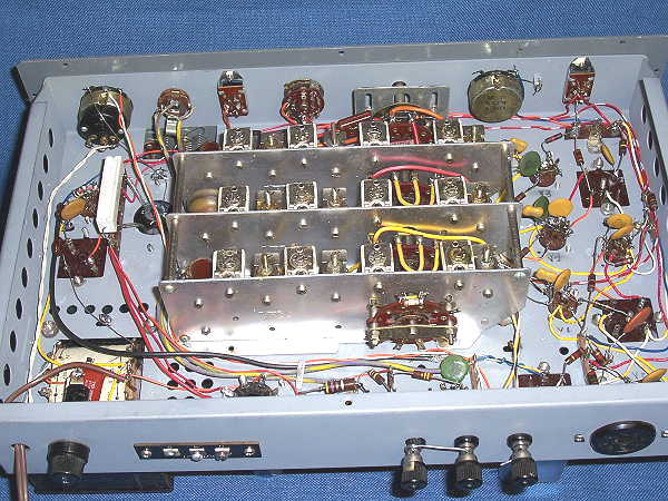
Upon arrival of the receiver, an inspection revealed that several modifications had been made to the circuitry. The BFO/ANL circuit had been re-wired for a 6C4 in place of the 6AV6, and a solid state diode substituted for the automatic noise limiter. The 6AV6 detector/first audio amp had been removed and the circuit re-wired for a 12AU7, I assume as a product detector for Single Side Band reception. A SS diode had been wired to use as an AM detector, a 6AQ5 had been substituted for the 6AR5 audio amp, and for some strange reason the 5Y3 rectifier was changed out for a 5U4 and several power resistors added to the power supply.
Powering up the receiver confirmed what I had suspected from the auction description, that the unit did not do well at all on receiving. I managed to pull in a few of the stronger local stations on the Broadcast band but only noise on the short wave bands. A quick check with the signal generator revealed that the IF frequency was adjusted to approximately 425 KHz instead of the required 455. After adjusting the IF transformers to the correct frequency, the unit did received better but still nowhere near what it should be capable of.
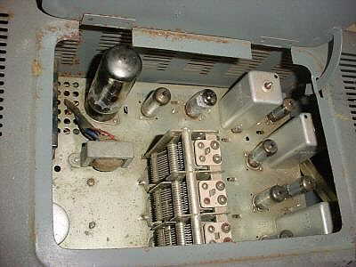
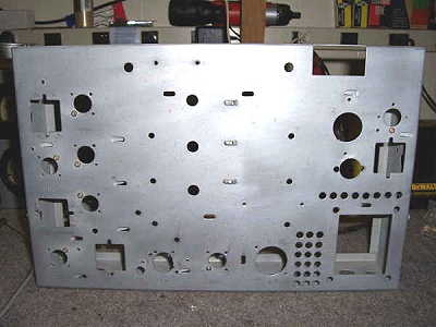
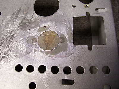
The physical condition of the unit wasn't too bad. The cabinet and front panel had some areas of missing paint, rust spots, and the usual scratches one would expect of a receiver of this age. There was an extra hole in the chassis next to the filter capacitor. The hole where the original detector/first audio tube had resided, had been enlarged for a 9 pin socket for the 12AU6. Three of the knobs were missing their trim rings.
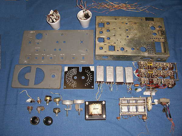
The pictures below show the condition of the unit.
|
|
|
I decided the best coarse of action would be to completely dismantle the receiver and start over from scratch. All components were removed from the chassis which was given to a friend to be sand-blasted.
|
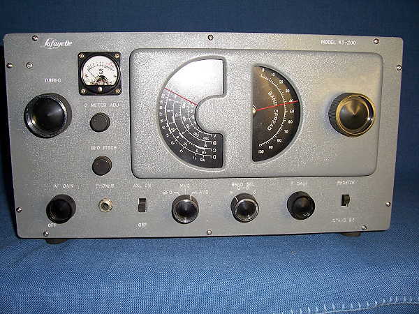
The front panel and cabinet were repainted. I used crinkle paint on the places where paint was missing, and I found a gray spray paint that matched the original color so close it was difficult to tell any difference. The lettering on the front panel was embossed into the paint, so the lettering remained intact. After the panel had dried, I used a scribe to remove the paint from the lettering. A can filter capacitor was gutted of the old insides and two new 47mfd@250VDC volt units were installed in the can and mounted over the original hole.
|
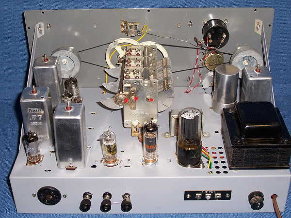
The chassis was painted a light gray. The following pictures show the final results of the rebuild.
|
|
|
|
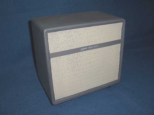
I was also lucky and found the HE-11 matching speaker on ebay. It was also repainted and a new speaker installed.
|
I received a great deal of pleasure out of restoring this little radio from my past. It was almost like opening up that new kit and getting the joy of building once again. After a complete alignment, the set performs like new and I have enjoyed listening to the short wave bands again using only a ten foot long antenna strung out on the basement floor. Time to think about getting a long wire up and pulling in some real DX.
|
 |