Restoring The Mosley CM-1
Amateur Radio Receiver
History
Mention the name Mosley to just about any amateur radio operator and they immediately think of antennas.
Mosley Electronics Inc., Bridgeton, MO., has been a manufacturer of radio antennas since the early 1950's and has been long known for their
great antenna designs for the amateur radio and commercial markets.
The CM-1 receiver was the brain child of McDonnell Douglas engineer John Clemens, W0DB (ex-W9ERN). After designing the receiver,
Clemens approached the Mosley company about manufacturing the unit. Clemens called it the Model CM-1 for Clemens Manufacturing,
dash 1 because it was the first model. The letters CM were also the initials of Carl Mosley owner of the Mosley company, so he of
course was happy with the model number.
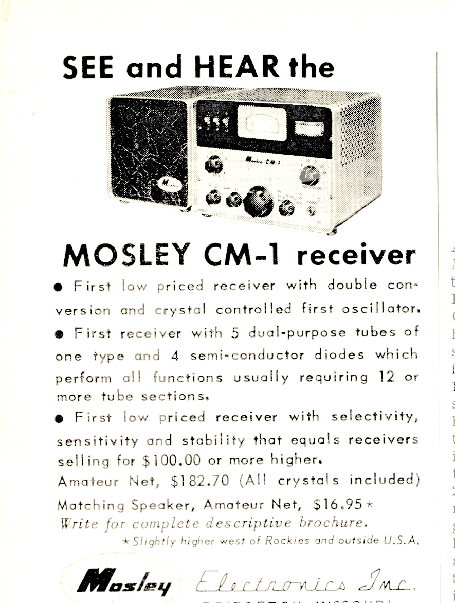
The receiver was introduced 1961, an ad in the April 1962 issue of Popular Electronics listed the price at $182.70. This
was Mosley's first attempt at producing a receiver, however due to a disappointing year of sales, it was only produced through 1962,
with about 1,000 units being sold, making it somewhat rare. That was the end of Mosley's adventure into the receiver business.
|
|
|
SPECIFICATIONS |
|
The CM-1 covers the 80 through 10 meter ham bands in seven 650 kc segments with a 12 inch circular tuning dial and also will tune
WWV at 15 MC. It also features an S-Meter, variable BFO, diode detector for AM, a product detector for SSB/CW, and a diode noise limiter.
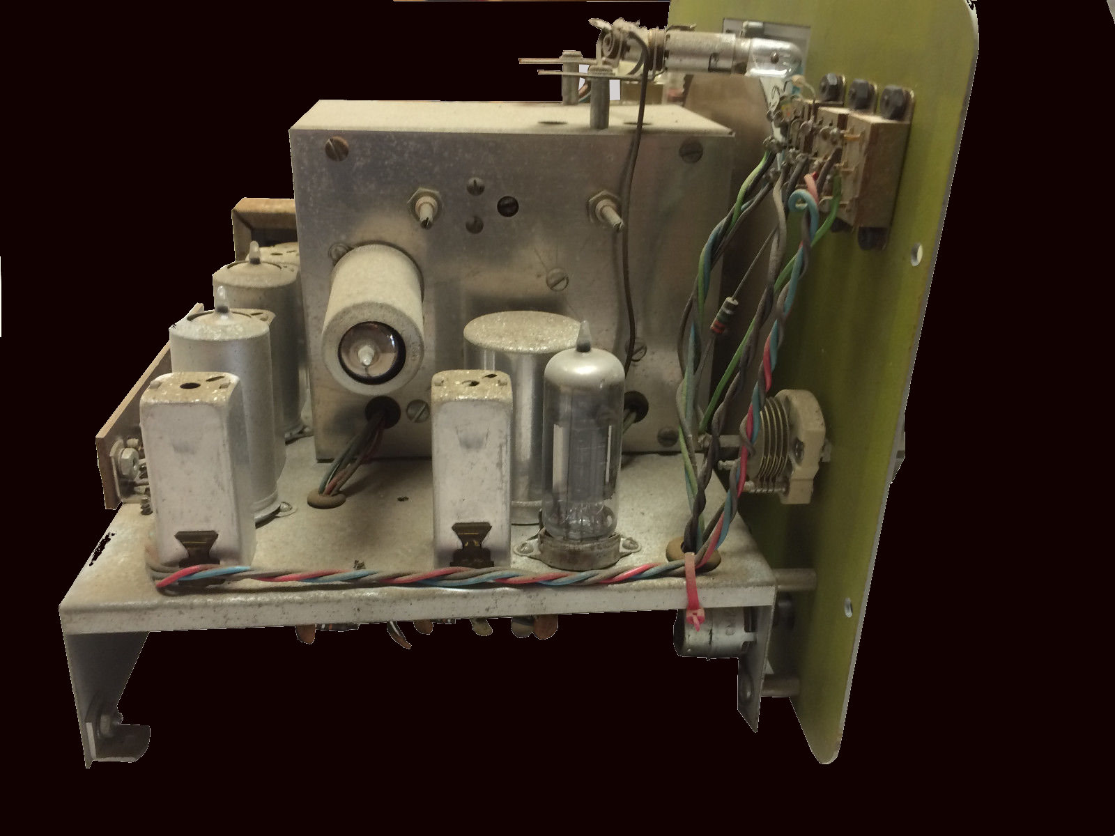
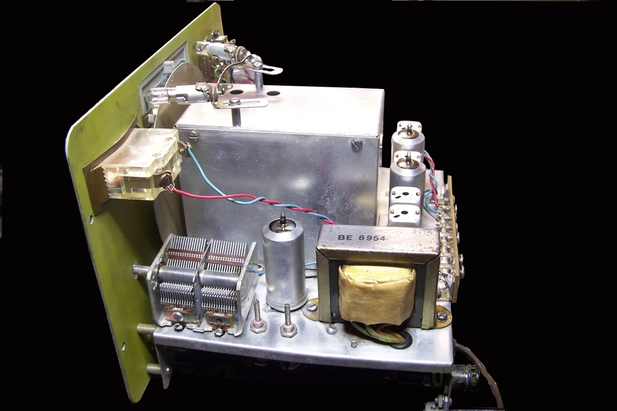
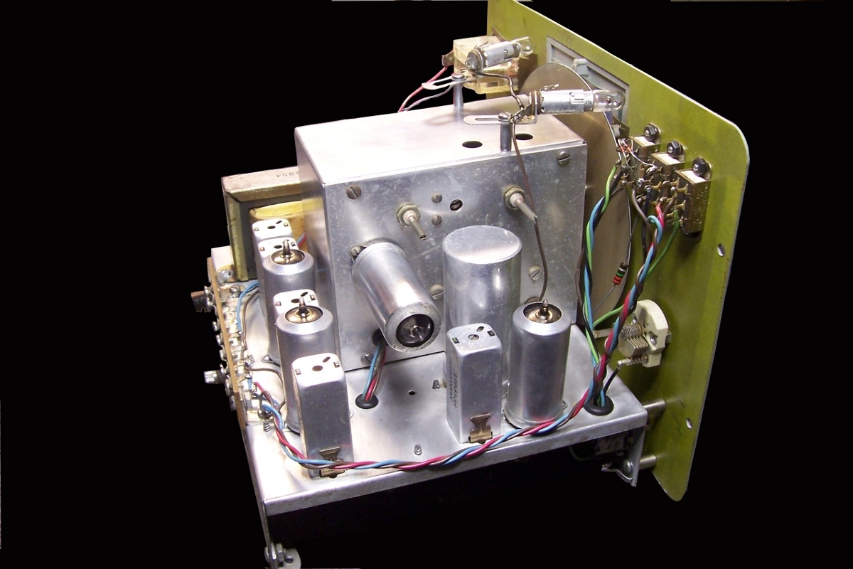
Under the chassis is where the uniqueness of this receiver manifests itself. The circuit design only uses five tubes, all type 6AW8A.
Each tube contains a triode and pentode section in one envelope, so ten tube performace is obtained.
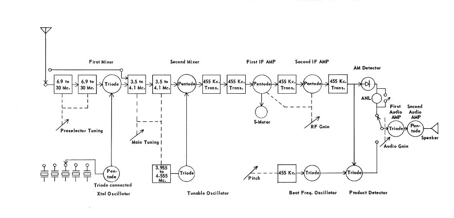
On 80 meters the CM-1 operates as a highly selective single conversion superhetrodyne receiver, the received signal bypassing the triode
crystal controlled converter. On the other bands the crystal controlled converter stage converts the 40, 20, 15 and 10 meter signals to
the 80 meter tuning range which becomes the first intermediate frequency. The second IF is 455 kc. There is no RF amplifier stage but the
low noise triode mixers and IF amplifiers provide plenty of gain.
See block diagram.
|
|
|
I had recently obtained my ham license in 1961 when this little receiver was introduced and saw the write-up by Herb Brier,
W9EGQ (Silent Key - 1977) in the April 1962 issue of Popular Electronics. I really wanted one of these receivers but being recently
married and on a rather tight budget, the cost was just to great. I would have to stick with my Lafayette KT-200 for the time being.
As time passed, the CM-1 fadded from memory, however interest was rekindled when one of the members of the Colorado Radio Collectors
Association turned up with a CM-1 at our annual vintage radio show a few years ago and sparked my interest in this little receiver
again. I began to keep an eye out at swap meets and on-line auctions when this unit turned up on eBay and I was the lucky winner.
|
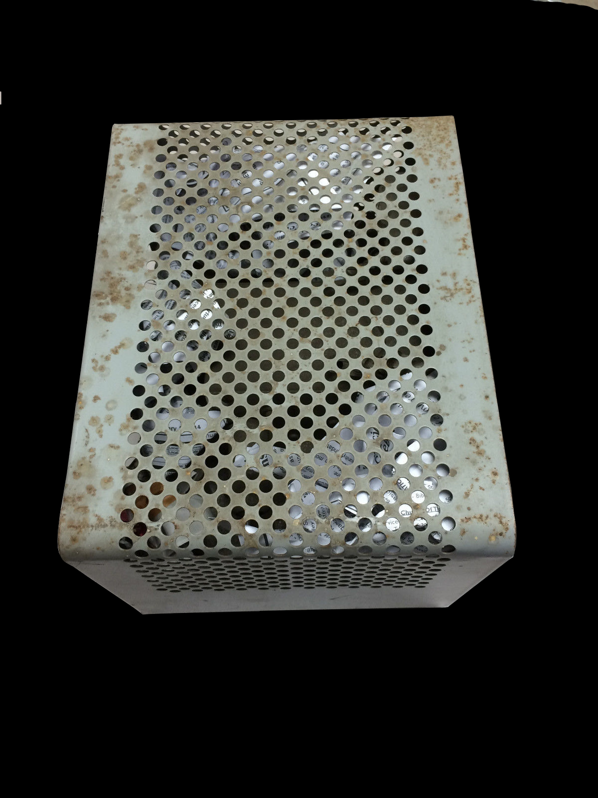
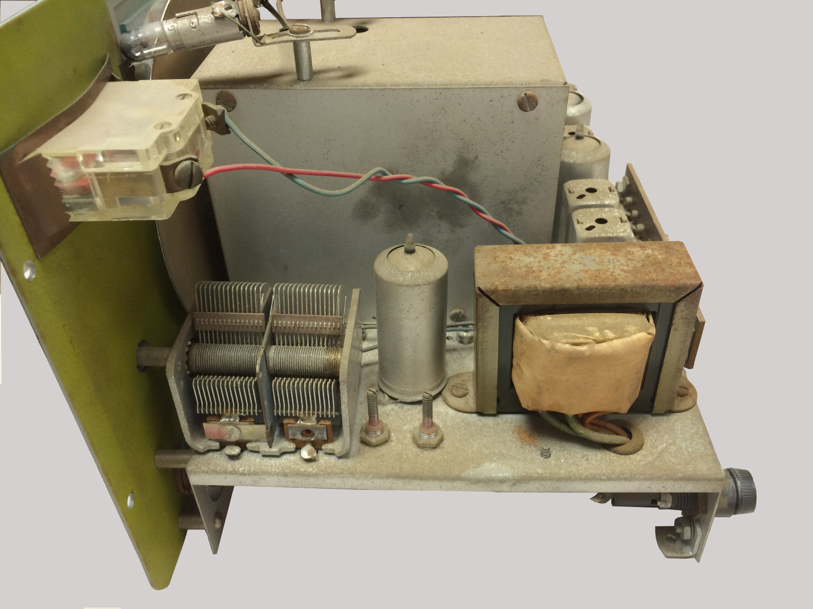
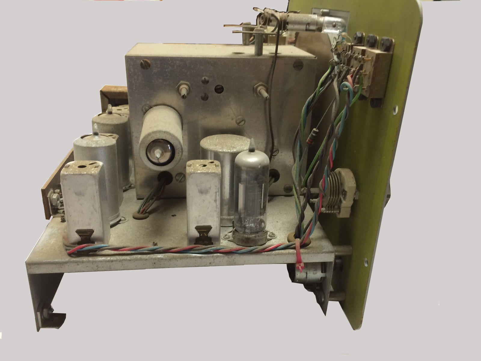
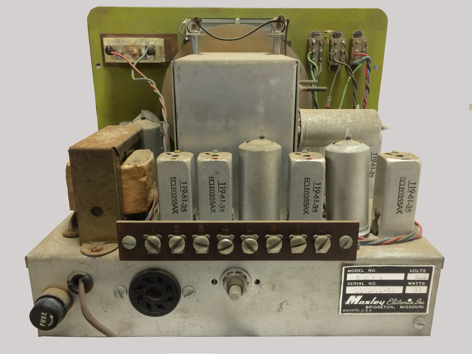
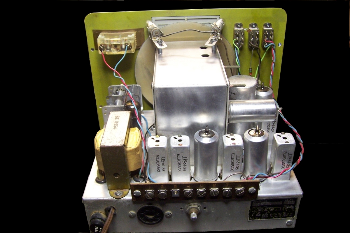
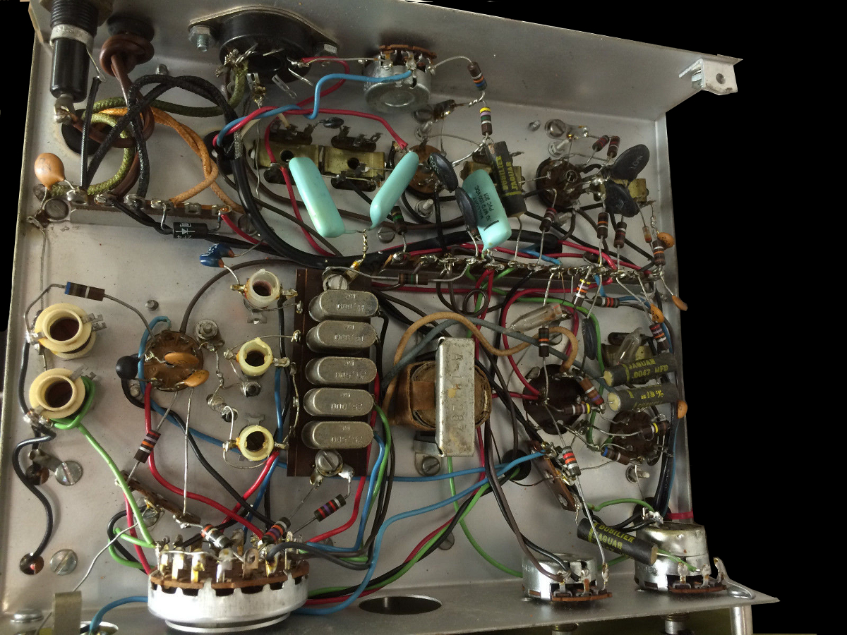
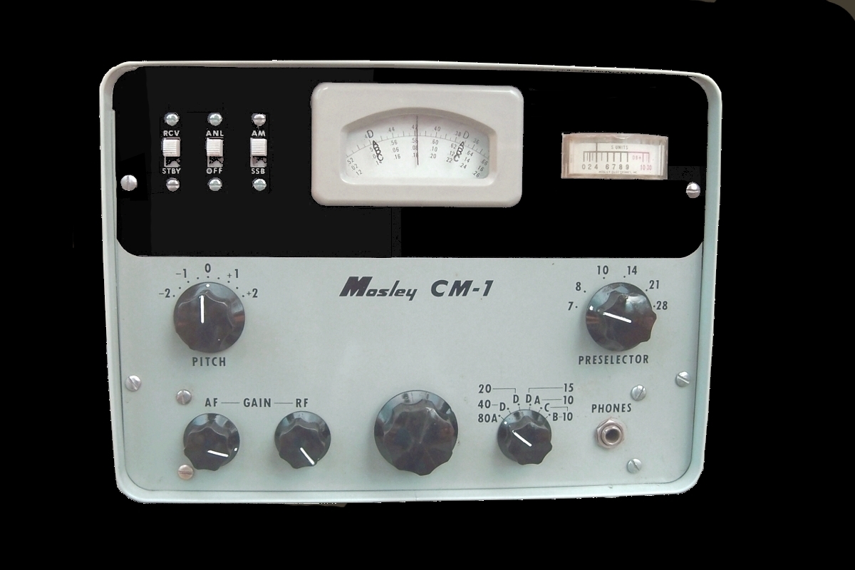
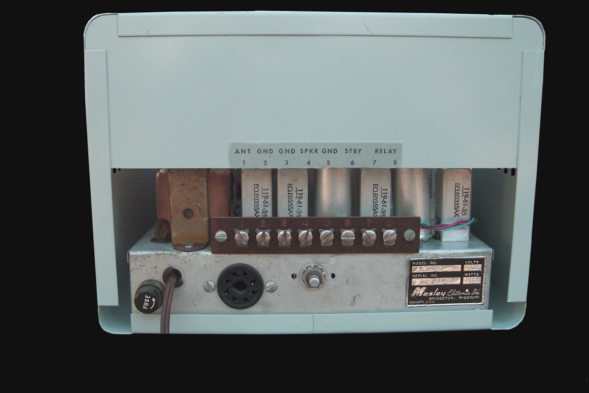
RestorationThe following pictures show the CM-1 as received. The paint on the cabinet was very rough and the top of the chassis had a heavy coating of dust and grime, however the front panel was in excellent condition and the underside of the chassis was very clean with no signs of modifications or of having been worked on. |
|
|
|
First order of the day was to check out the unit to see if it would power up and receive. I attempted to power the unit up using the Variac
but there was no current draw...I began to suspect maybe an open primary on the power transformer. Testing the primary showed good continuity
and the problem turned out to be a defective on/off switch. I shorted the switch and then the unit powered up, current draw was within
limits and the B+ voltage came up to specs, however there was hum in the speaker but the receiver was dead. I pulled the tube shields and
found one tube with an unlit filament. I moved the tube around in the socket and the filament would light intermittenly.
Cleaning the tube pins and the socket cured that problem, but still no receive. Testing the tubes found one dead 6AW8, replacing that
I could now hear background noise.
The filter capacitor was changed out to clear up the hum problem. The capacitor was a can type with four sections, 50 mfd @ 150vdc (3) and
25 mfd @ 25 vdc. Scrounging through the junk box produced a new old stock four section can capacitor at 20 mfd @ 450 vdc, with a manufacturer
date of 1971.
Being that old I checked it for leakage, capacitance, and power factor which all sections met specifications, so it replaced the original filter.
Since the new capacitor had a lower capacitance rating then the original (20 mfd vs 50 mfd), I changed the rectifier circuit from a half wave
diode to a full wave bridge diode circuit. This eleminated the hum and should also reduce stress on the rather small power transformer.
The paper capacitors were also replaced, inserting new capacitors into the original cardboard sleeves.
|
|||||||||||||||||||||||||||||||||||||||||||||||||
|
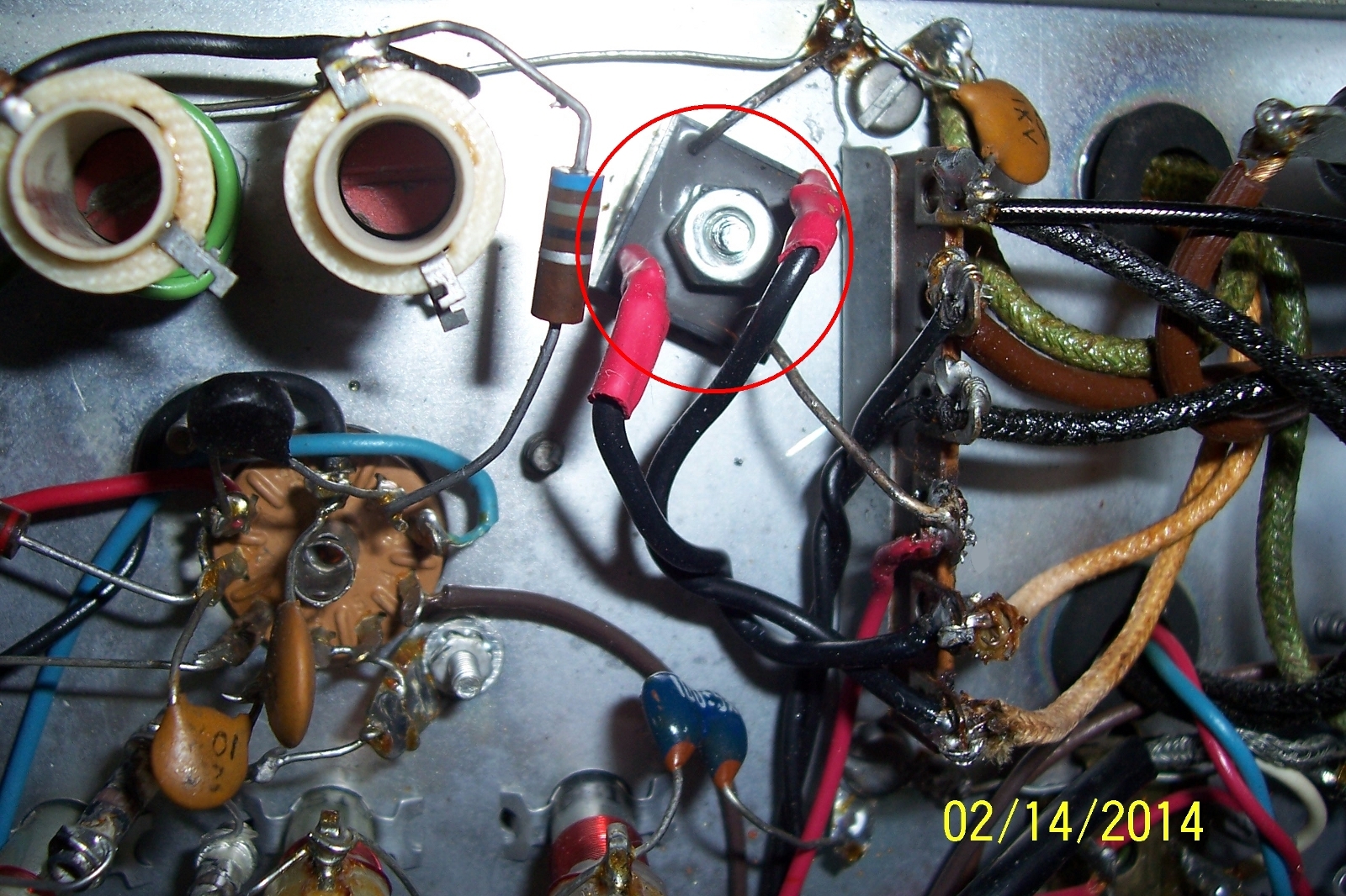
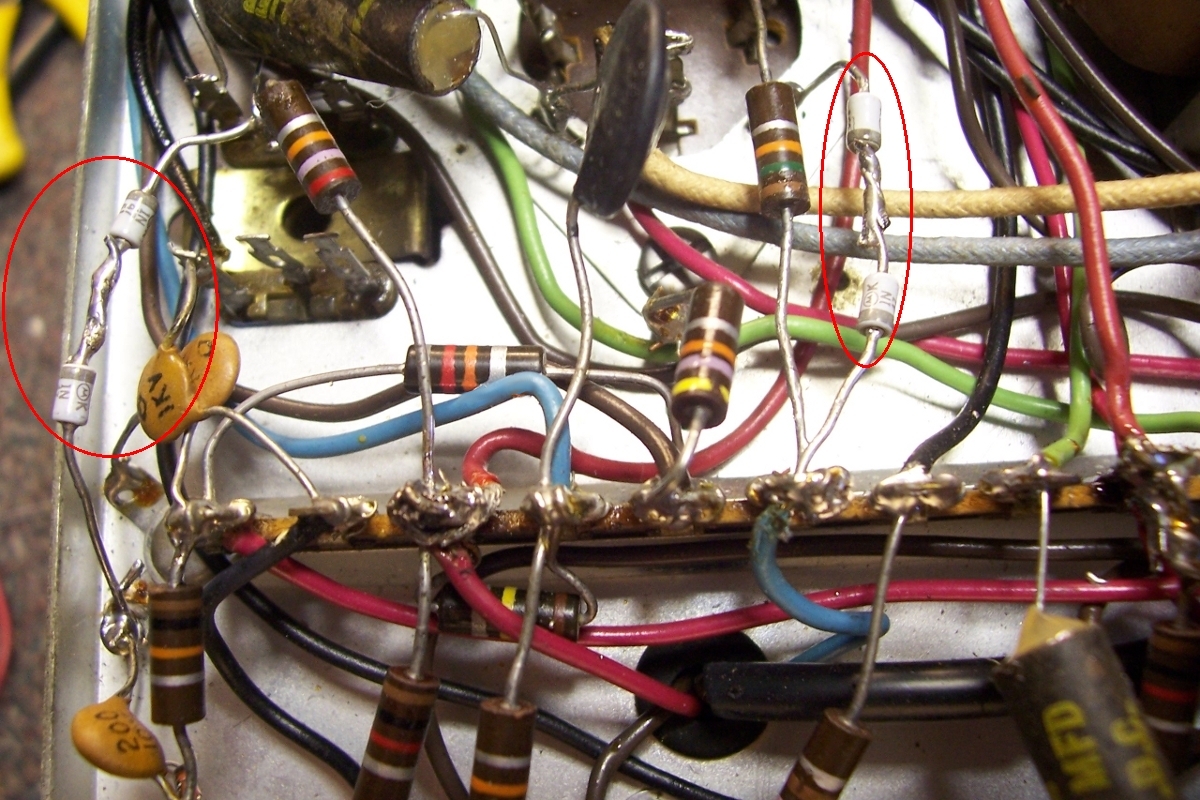
The B+ voltage for the VFO and BFO is regulated by two neon lamps, neither of which were working. One had a lead broken off at the glass envelope and the other would not fire to regulate the voltage. I replace the neons with zener diodes and a check of all voltages showed everything to be within specifications. |
||||||||||||||||||||||||||||||||||||||||||||||||||
|
|
After a full alignment, the receiver was connected to the 40 meter dipole antenna, tuning the 40 and 15 meter bands brought in many strong signals. Time to move on to the cosmetic restoration. |
|||||||||||||||||||||||||||||||||||||||||||||||||
|
|
|
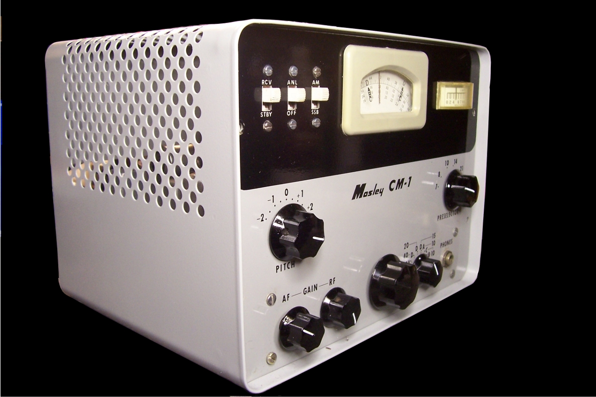
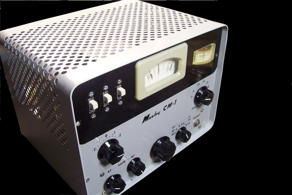
The cabinet was stripped and lightly sanded to remove any surface rust, and painted with "light gray" enamel paint, which is a very close match to the original color. The final results are shown below. |
||||||||||||||||||||||||||||||||||||||||||||||||||
|
Final ThoughtsResults with this little receiver have been quite suprising. It is very sensitive, the AM and SSB performance is excellent, and after warm up, very stable. It's performace compares quite well against an R.L. Drake 2-B, as I can copy any signal on the CM-1 that can be copied on the 2-B. Due to lack of any filters, only the 455 kHz IF transformers, the selectivity is just fair making it somewhat difficult to seperate stations on a really crowded band. Because of the conversion scheme, it may be possible for strong 80 meters signals to come through on other bands, but I have not experienced this. The receiver has been quite fun to use on AM paired with a Viking Ranger AM transmitter. Why the CM-1 was a poor seller is anyone's guess, but at the time ham gear was big and heavy and there was an attitude among some that if it wasn't big and weighed a ton then it couldn't be a good performer. The Drake 1-A, 2-A and 2-B receives were some of the first small high performance receivers of that era, had a successful career, are still sought after today mostly by the AM crowd and still bring good prices. It could have been the styling of the CM-1 that turned some off or maybe it was thought that a receiver that only used five of the same type tubes just could not be a good performer. I believe the receiver was a sleeper at a good price for the day that a lot of hams missed out on. | ||||||||||||||||||||||||||||||||||||||||||||||||||
I welcome your comments, if you have a moment
please read/sign the guest book.
|
|
