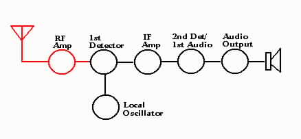
Troubleshooting the RF Amplifier Stage
 |
|
 |
| Symptom | Abnormal Reading | Possible Cause |
|---|---|---|
| RF Stage Inoperative | Plate voltage = 0. Other voltages normal | Open primary (L4) of interstage
transformer T-2. Open plate resistor R-4. Plate de-coupling capacitor C-4 shorted |
| Screen voltage = 0. Other voltages normal | Screen by-pass capacitor C-14 shorted. Screen resistor R-14 open | |
| All voltages normal | Check for short in gang
tuning capacitor C-2. Defective tube | |
| Cathode high | Open cathode resistor R-1 | |
| Cathode voltage = 0 | Shorted cathode by-pass
capacitor C-1 Dead tube | |
| Weak signal | All voltages normal | Weak tube. Check for open winding (L1-L2) on antenna transformer T-1. Open plate by-pass capacitor C-4. Open AVC by-pass capacitor C-30. RF stage out of alignment |
| Oscillation | All voltages normal | Open screen by-pass capacitor C-14. Tube shield not making good ground connection. |
| Noisy operation | All voltages normal | Open or corroded antenna transformer T-1. Open AVC by-pass capacitor C-30. Corrosion in the interstage transformer T-2. Defective tube. Defective gang tuning capacitor C-2 (check for grounding wipers making poor contact). Dirty trimmer capacitor C-2A |
| Poor tone quality | All voltages normal | Shorted AVC by-pass capacitor C-30. |
| Tube element | Pin No. | Voltage |
|---|---|---|
| Plate | 3 | 240 |
| Screen | 4 | 100 |
| Cathode | 8 | 3 |
   |