![[ve301ad]](images/ve301/ve301ad-4.jpg)
![[ve301instruction]](images/ve301/ve301ad-small.jpg)
In the 1930's, radio in Germany was used not only for entertainment but to broadcast political propaganda throughout the country. After Hitler came to power in 1933, the government took over all independent broadcasting companies and political propaganda programs dominated the air-waves.
There was no better way to reach the mass population than by radio, however few could afford the current receivers available which were quite expensive. There needed to be an inexpensive radio that anyone could afford, so the People Receiver was developed. Several models of these low cost radios were produced between the years 1933 and 1944.
I found this VE301W on eBay. The auction had the "Make Offer" option so I made an offer which was accepted by the seller. The radio was well packed and arrived just as shown and described in the auction.
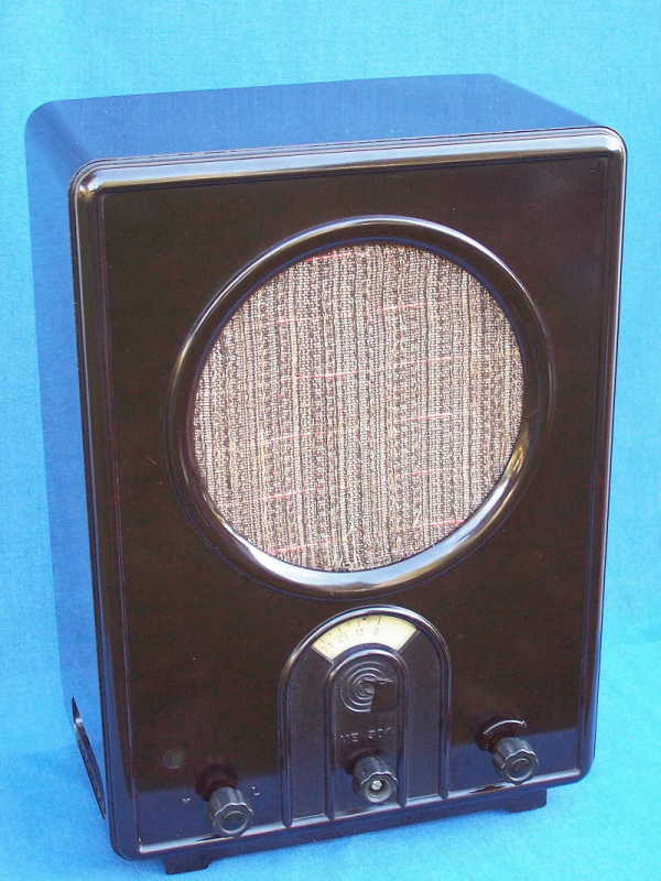
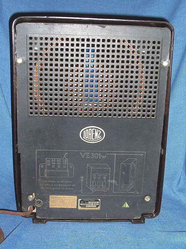
Model: Körting VE301W (the 301 signifies the date 30.1.1933 that Hitler's party came into power)
Production years: 1933 to 1937
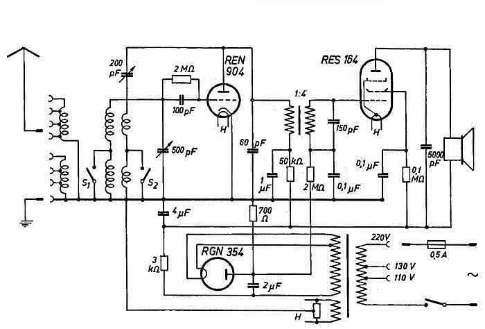
Circuit: Regenerative
Power: 110 - 220 volts, AC 50/60 cps
Tuning range: Long Wave (approx 150 - 530 kc) /Medium Wave (approx 455 - 1800 kc).
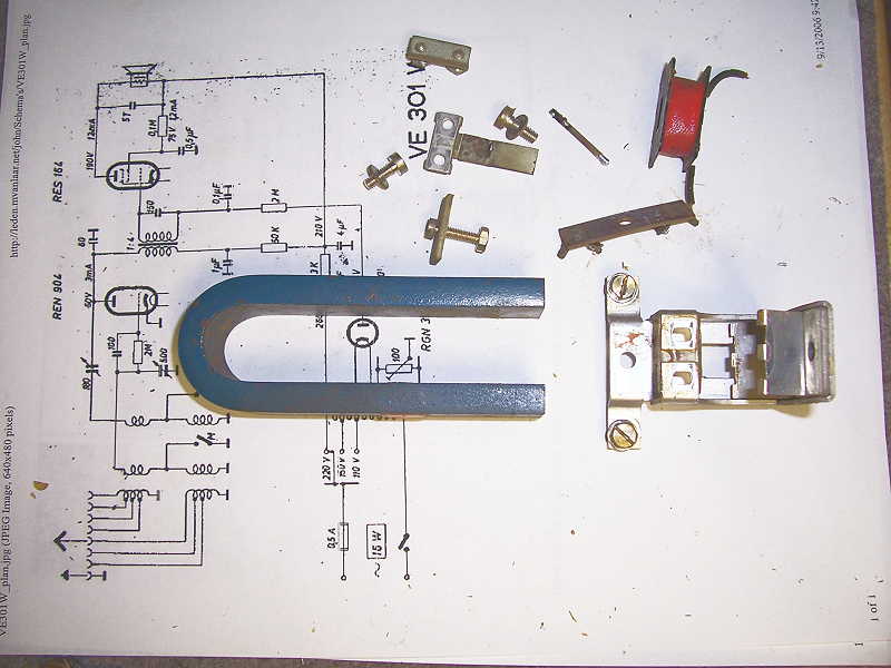
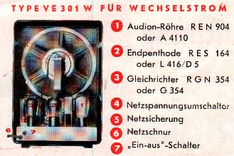
Tube line-up: RES 164 audio amp - RGN 354 half wave rectifier - REN 904 triode regen.
Selling Price: 76, RM (Rentenmark, approximately $18 U.S.)
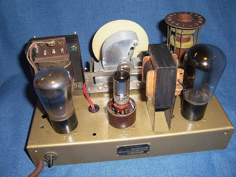
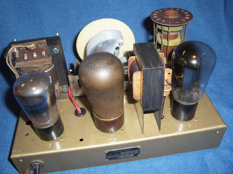
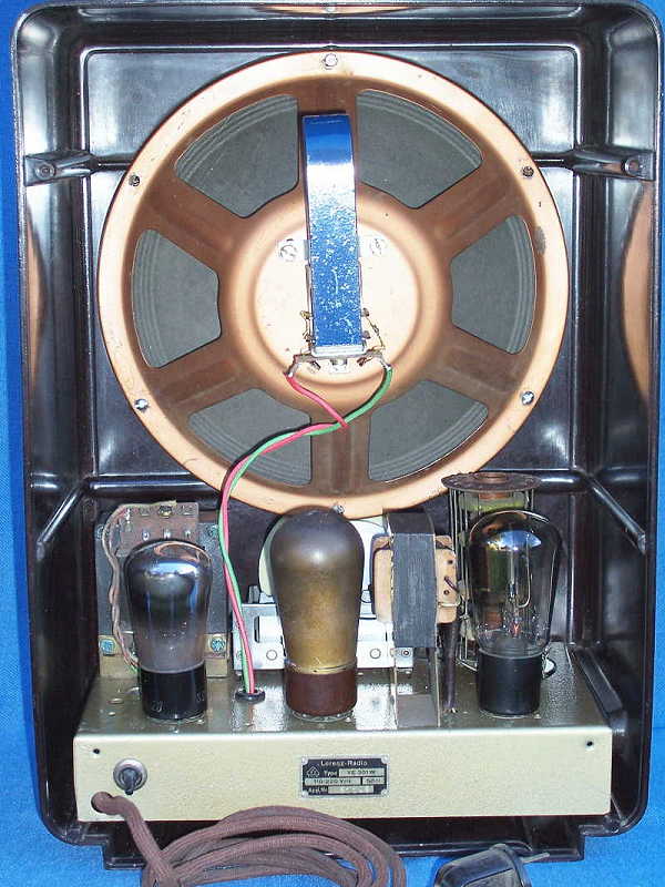
The chassis is transformer powered with taps on the primary to allow use on 220, 130, and 110 volts ac. The RGN 354 is a half wave rectifier, the filament voltage is taken from a tap on the high voltage secondary winding (see schematic). The case is dark Bakelite measuring 15 1/2 inches high, 11 inches width, and 6 1/4 inches deep. The circuit is a one tube regenerative detector using the REN 904 triode, audio is coupled from the REN 904 to the RES 164 audio amp through a 1:4 ratio interstage transformer.
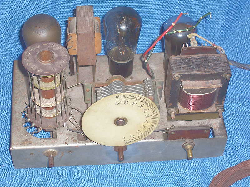
The radio was carefully unpacked and given a good inspection. One of the knobs was missing the insert and there was a hole in the cabinet on the lower left front that had been poorly patched. This had all been shown and noted in the auction description. Other than that, the receiver looked to be in very good condition. The chassis had the usual expected amount of dust, some rust spots and the plating was flaking off in several places.
Click thumbnail for larger image
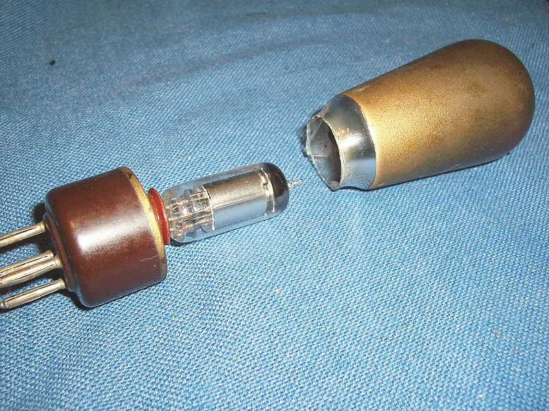
I wanted to verify if the regen circuit was working so the signal tracer was connected to the plate circuit of the first tube (REN 904) but there was no output. Since the coating on the envelope prevented seeing the filament, a check with the ohm-meter showed it had no continuity. The tube in socket number 2 where the RES 164 should reside has a clear envelope and upon closer inspection it certainly appeared to be a triode instead of a pentode like a RES 164, as all I can see is one grid. There are no markings on the tube but I came to the conclusion this is actually another 904 triode. This tube was moved to socket number 1 and now the regenerative circuit is working as I can trace signals all the way through the interstage transformer to the grid pin of socket number 2, where a RES 164 should reside. So I have two 904 tubes, of which one is defective.
I wondered if there was a modern tube that could substitute in place of a 164. A scan through the tube manual revealed that a 3V4 seven pin miniature battery power pentode might be a good candidate. A 3V4 kludged into the 164 socket wouldn't look very original. As I had a defective 904 tube, I surmise that if I can re-stuff capacitor cans, maybe stuffing a 3V4 into the 904 to make a "custom" 164 might be feasible. I figure nothing ventured, nothing gained.
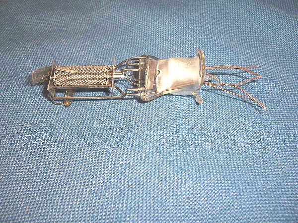
The element wires of the defective 904 were un-soldered from the tube base pins, the base was loosened and removed. A Dremel tool with a cutting disk was used to carefully cut the bottom of the glass envelope and remove the tube elements. Next a seven pin socket was wired into the base. The 904 and 164 require 4 volts on the filament and since the 3V4 only needs 2.8 volts, a 22 ohm resistor was wired inside the base in series with the filament which dropped the voltage to just under 2.8 volts.
The other pins of the seven pin socket were wired to the base to correspond with a 164, the tube was installed and power applied. Again the signal tracer was used to check for a signal on the output, but nothing was heard. A voltage check reveled there was no B plus on the plate of the 164/3V4 tube. This led me to suspect the speaker voice coil was defective.
Click thumbnail for larger image
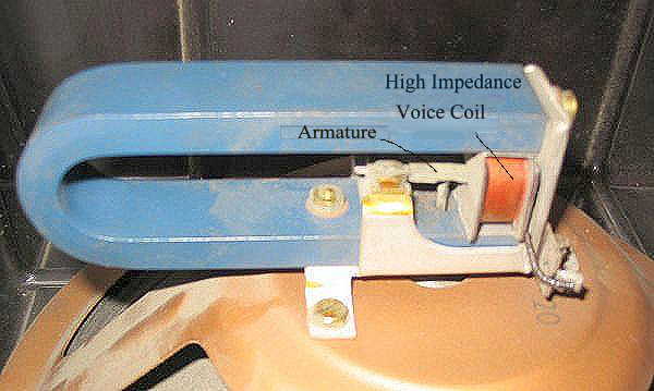
The speaker is of the high impedance voice coil type where the voice coil is in series with the B plus going to the plate of the output tube. The varying audio current through the voice coil acts on an armateur in the center of the coil. This armature is connected to the speaker cone via a small metal rod which transfers the motion of the armature to the speaker. No B plus is a good, or should I say bad, indication that the coil is open. A check with the ohm-meter confirms that it is indeed open and I am not too excited about the prospect of having to rewind the coil.
Click thumbnail for larger image
The speaker is set aside to be dealt with later, and for the time being a 2,000 ohm resistor is substituted in place of the speaker coil and the signal tracer connected for audio output. Powering up again there is now B plus on the plate and screen grid of the 164/3V4 and several stations are heard on the Medium Wave (broadcast) band through the signal tracer. Success at last! The empty glass envelope is installed over the 3V4 and a bit of hot glue holds the envelope to the base, and no one would guess that a 3V4 is now doing the work of a 164.
Click thumbnail for larger image
A check on eBay found a 164 by a seller in Germany, so I know that they are available and the price seems very reasonable. Perhaps at a future date I will replace the "custom" 164/3V4 with the real thing.
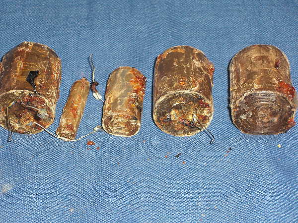
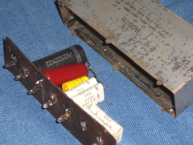
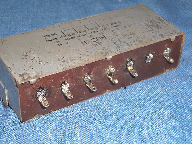
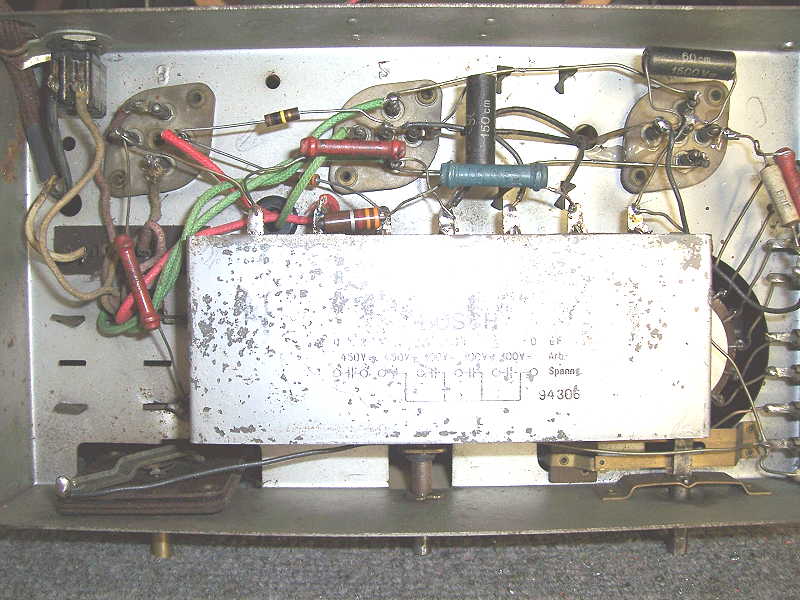
Attention is now turned to the large capacitor can that dominates the underside of the chassis. Luckily there is a diagram on the can giving the values and hookup of the capacitors to the terminals. The can is removed and the fold over tabs are opened and the cover removed along with the old capacitors. The old capacitors are removed and new capacitors installed in their place. The cover is replaced and sealed with the tabs and the can and is set aside as the screws that hold the tuning capacitor can only be accessed with the capacator can removed.
Click thumbnail for larger image
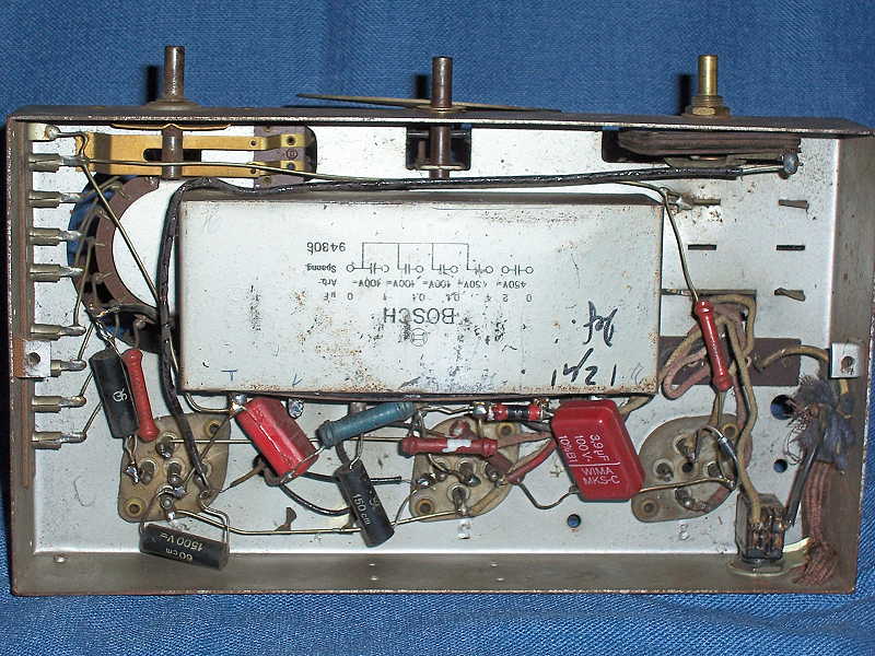
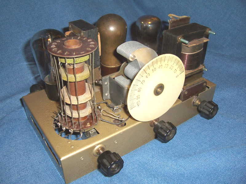
The tuning capacitor is removed and placed in a solution of Navel Jelly thinned with water to soak overnight. After soaking, it was rinsed with water, dried with a heat gun and lubricated. Navel Jelly was used along with steel wool on the chassis to remove the rust and any loose plating. Next the chassis was masked for painting. I tried chrome paint but it turned out looking just like a chassis that had been painted with chrome paint, so I opted for hammertone gold instead. The tuning capacitor and the capacitor can were re-installed. The red capacitors that can be seen in the photo were there to replace defective units in the capacitor can, so these were removed and the wiring returned to its orginal state. Now with the chassis restored, it is time to turn attention to the speaker and the open voice coil.
Click thumbnail for larger image
The magnet and coil assembly would have to be dis-assembled to gain access to the coil. The dis-assemmbely wasn't too difficult, the only hard part being un-soldering and removing the rod connecting the armature to the speaker cone. The Morris Coil Winder was set up to unwind the coil and count turns. The outer insulation was removed and unwinding began. At approximately one hundred turns a break in the wire was discovered. Could there hopefully be only one break? The ohm-meter confirmed there was as I could now read 2,000 ohm through the coil. The turns removed wouldn't be missed as far as operation was concerned, so the fine coil wire was cleaned of enamel and soldered to the external lead and the outer insulation replaced. The speaker was re-assembled and connected into the circuit and it played loud and clear.
Click thumbnail for larger image
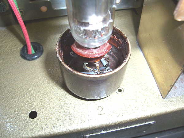
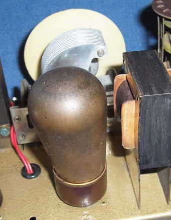
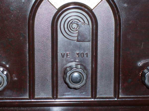
With the chassis now restored and speaker repaired, attention was turned to the cabinet. Except for the hole on the lower left front that had been badly repaired, the cabinet was in very good condition. I removed what ever it was that had been use to patch the hole and used a reamer to smooth out the edges. A piece of thin balsa wood was glued over the hole on the inside of the cabinet and fiberglass resin was poured into the hole and left to cure over night. After curing the balsa was sanded away and on the front the resin was sanded smooth. Black paint with a slight bit of burnt umber added was use to paint over the resin both front and back. Novus #2 Polish And Scratch Remover was use to polish up the cabinet, followed by a coat of paste wax. One of the knobs was missing the insert and I found a black nylon hole plug at the local hardware store that with a little modification fit perfectly. To remove a knob, first remove the insert and then loosen the screw and the knob slips easily off of the shaft. The picture below shows a knob with the insert removed revealing the screw.
Click thumbnail for larger image
The speaker grill cloth was quite faded, however on the back side where it had been protected it looked quite good. Acetone was used to soften the glue and the cloth was reversed. The speaker and chassis were installed in the cabinet and with the restoration complete an outside long wire antenna was connected and the set pulled in stations all across the Medium-Wave (broadcast) band.
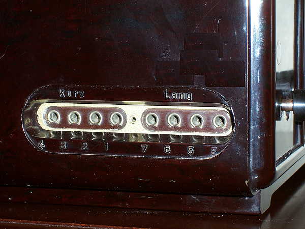
There is no volumn control in the audio circuit, however volumn can be varied to some degree with adjustment of the regeneration control and by moving the antenna to different taps on the antenna input.
Click thumbnail for larger image
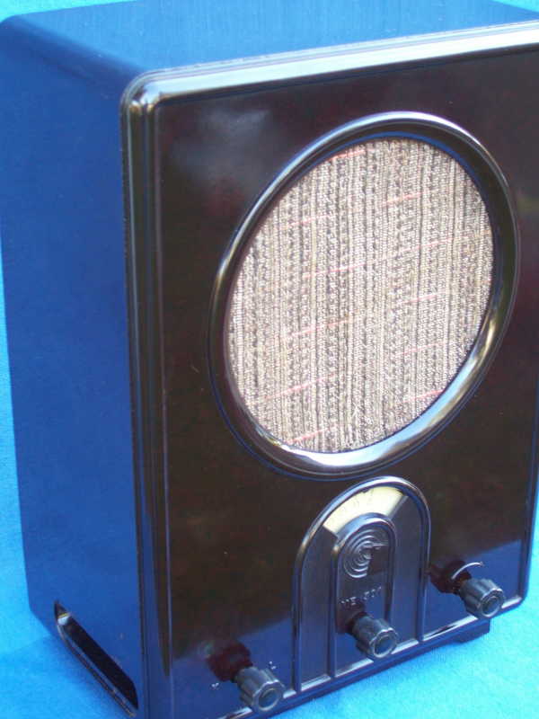
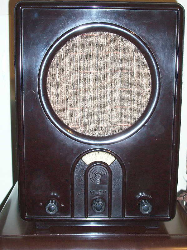
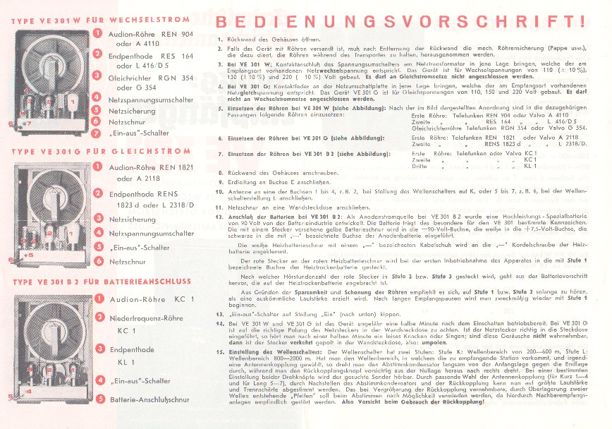
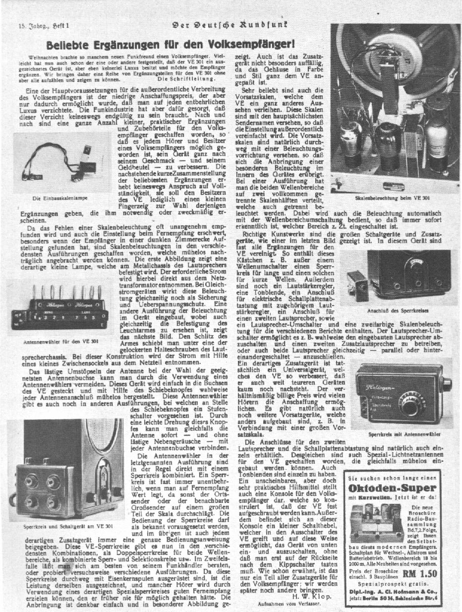
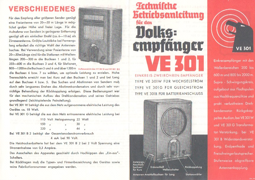
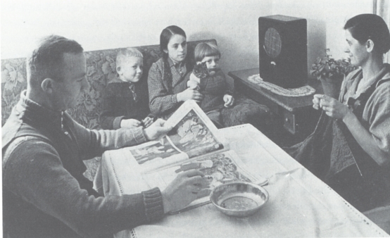
Below are pictures of the restored receiver along with some German language instructions and advertisement for the radio and a photo of a German family listening to their VE301.
Click thumbnail for larger image
 |