 |
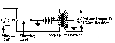
Some provision must be made to supply the high-voltage direct current required to operate the plate circuits of the receiver. Since a steady DC voltage applied to a transformer will not induce a voltage in the secondary, a means must be provided to interrupt and alternately reverse the DC voltage in the primary winding. The vibrator will accomplish this. Refer to Figure 1 below.
 |
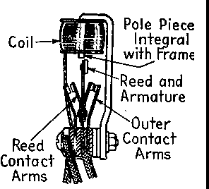
How the Vibrator Works - At the starting position, current flows through the top half of the transformer primary to the vibrator coil. This causes the vibrator contacts to be attracted upwards, making the top contact. The top contact shorts out the vibrator coil, and causes a heavy current to flow through the top half of the primary winding. The de-energized vibrator coil allows the vibrator contacts to swing through the starting position, and make contact with the lower contact. This interrupts the current through the top half of the primary winding and causes a heavy current to flow through the bottom half of the primary winding, reversing the magnetic field. This also removes the short across the vibrator coil, allowing it to once again energize, attracting the contacts upward. This cycle repeats itself continuously. The constant reversal of the magnetic field induces an alternating current in the secondary of the transformer. The frequency of this alternating voltage is determined by the mechanical structure of the vibrator. See Figure 2 below.
 |
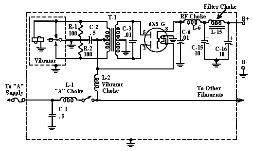
The vibrator and transformer convert the 6-volt DC to a high-voltage alternating current. This is fed to a conventional rectifier and filter circuit to provide the B+ voltage for the radio set. See Figure 3 below.
 |
Vibrator Hash - The making and breaking of current at the vibrator contacts are accompanied by sparking. The sparking decreases the life of the contacts and causes RF interference in the receiver. This interference is know as hash. Circuits must be provided for spark suppression and hash filtering.
C-3 in the diagram above is the buffer capacitor. It takes up the high-voltage surges that would otherwise result from the rapid magnetic changes taking place during the time the vibrator contacts are traveling between contacts. It also is effective in reducing sparking at the contacts. The capacitor and inductance of the transformer form an oscillating circuit, and for this reason it is important that this capacitor be replaced with one of the same value and voltage rating. Common values vary from .005 to .03 mfd.
Resistors R-1 and R-2 are connected across the vibrator contacts and are also effective in reducing sparking and hash. They form a discharge path for back electromotive force in the primary which would otherwise cause a heavier spark at the contact break. These resistors rarely give problems. Sometimes capacitors are used in place of the resistors.
The vibrator choke L-2 and C-3 form a hash filter to keep the hash from the vibrator out of the receiver filament lead.
Other methods for hash suppression are the total shielding of the vibrator and sometimes the power supply itself. The vibrator is shielding by being enclosed in a metal can. The entire power supply is often shielded by being enclosed in a metal compartment of the receiver assembly.
The Rectifier and Filter - The 6X5 tube is widely used as a rectifier in vibrator supplies with the 6Z4 and 84 types also used. Receivers using loctal type tubes may use a 7Y4.
The filter is the standard L-C filter circuit to smooth the rectifier output. It consists of the filter choke L-15 and electrolytic capacitors C-15 and C-16. In some receivers, the choke may be the speaker field coil. RF choke L-6 and C-6 form an RF filter for hash suppression in the B+ lead.
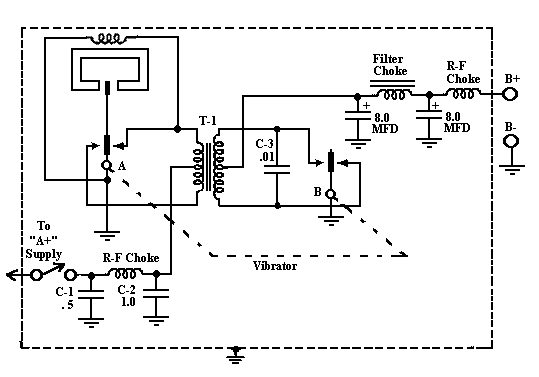
The Synchronous Vibrator Power Supply - The synchronous vibrator has an extra set of points that take the place of the rectifier tube. This acts as a mechanical rectifier. The circuit is shown in Figure 4 below. Both sets of contacts are mounted on the same vibrating reed and operate in sync, as indicated by the dashed line in the diagram. The second set of contacts at B cause the secondary current to always flow through the load in the same direction. In this manner, the contacts at B serve as a full-wave rectifier, eliminating the need for a rectifier tube.
In radio with a synchronous vibrator power supply, the polarity of the input voltage is important since it will determine the rectified output. Incorrect polarity will cause the rectified output to be minus. In a set with a non-synchronous vibrator power supply, the input polarity does not matter.
 |
Troubles Common to Vibrators - Vibrators are subject to many ills. Shorts and overloads in the B circuit of the receiver place an abnormally heavy load on the vibrator. In addition, it is a mechanical component that is in constant motion, and deterioration due to wear is to be expected. The spring of the vibrating reed can lose its tension, the contact points wear, and sometimes become black and pitted and stick. Sometimes a defective vibrator can be repaired by filing the contact points. This means you must open the container and remove the vibrator unit. Use a burnishing tool to clean the points as anything else such as fine sandpaper or a file will remove the coating on the contacts. A weak vibrating reed or worn contacts may cause the vibrator not to start. A good 6-volt vibrator should start and run at 4-volts DC. It is advisable to fuse the A supply input; should the vibrator contacts stick, heavy current will be drawn that could cause damage to components.
There are solid state replacements available for non-synchronous vibrators. Antique Electronics Supply is one source of these units.
Troubles Common To The Buffer Capacitor - The buffer capacitor usually breaks down due to voltage overload. When this happens the radio is inoperative because of the absence of B+ voltage. Heavier than normal current will be drawn because of the short across the transformer secondary. A shorted buffer capacitor will be evident by measuring resistance from plate to plate of the rectifier tube. The capacitor should be replaced with one of the same capacity value and the same or higher voltage rating. The voltage ratings for buffer capacitors are in the 1600 volt range.
Troubles Common To The Rectifier Tube - Troubles with the rectifier tube are the same as in other AC operated receivers. Weak or no electron emission and open filament are the most common problems with rectifiers.
Troubles Common To The Filter Circuit - Filter chokes seldom give any problems. The electrolytic capacitors, however, can open, become leaky, or short. When replacing filter capacitors, it is important that the replacement has the same or higher voltage rating.
Trouble Common To The Power Switch - The power switch in vibrator power supply receivers is prone to give more trouble than in AC operated receivers. This is because the switch must break a heavier current, in the order of 3-6 amps, whereas the AC operated receiver must only break in the order of .3 to 1 amp. In addition, any slight resistance developed in the switch contacts of an AC operated receiver will be overridden by the 115 volts supply without any appreciable heating of the contact. The same circumstance in the low-voltage, high-current of the vibrator supply will cause considerable loss of power, heating and finally burning of the switch contacts.
Hash Suppression - Different receivers use various types of hash suppression methods. A breakdown of one or more of the hash suppression components can cause excessive hash in the set. When restoring a set it is advisable to replace all of the capacitors in the hash suppression circuits. Try to use values as close to the original as possible. Check all ground connections. Some ground connections may be established by chassis screws; some may be soldered directly to the chassis. Occasionally, a chassis rivet may be used for a ground connection. These should be cleaned and spot-soldered to the chassis. If excessive hash persists, try changing the rectifier tube or the vibrator, if another is available. If resistors are used across the vibrator contacts, check these for open or changed values.
Quick Check Of The Vibrator Power Supply
| Symptom | Incorrect check results | Check for |
|---|---|---|
| Receiver does not operate | No buzz from vibrator | Blown or defective fuse Burnt or inoperative switch Defective or worn vibrator |
| One or more tubes do not light | Defective tubes Defective filament wiring | |
| B plus measures low or zero | Shorted buffer capacitor. Worn-out vibrator. Defective rectifier tube. Short-circuited RF hash by-pass capacitor in B plus lead. Shorted filter capacitor. Short in receiver portion of B plus circuit. | |
| Power supply checks give normal results | Trouble in the receiver stages | |
| Receiver operation is weak | Low or erratic B voltage | Worn out vibrator. Weak rectifier tube. Resistance in switch. Incorrect capacity of buffer capacitor. Component in receiver drawing too much B current. |
| Power supply checks give normal results | Trouble in the receiver stages | |
| Excessive hum | Open filter
capacitors. Defective tubes. Poor ground connections in receiver | |
| Excessive hash | Poor ground
connections. Defective vibrator. Defective rectifier tube. Open hash filter. Incorrect buffer capacitor. | |
| Intermittent operation | Power supply checks give normal results | Worn-out vibrator which sometimes fails to start (check at 4 volts). |
| Fuse blows repeatedly | Power supply checks give normal results | Vibrator with sticking points. Intermittent cathode to heater short in rectifier tube |
| Point to Point | 6X5 pin No. | Voltage |
|---|---|---|
| Chassis to "A" supply hot lead | 6 | |
| Chassis to center tap of transformer primary | 5.5 | |
| Chassis to rectifier plates | 3 & 5 | 150-250 AC |
| Chassis to rectifier cathode | 8 | 160-260 |
| Chassis to B plus | 150-250 |
  |