The receiver uses two 6SK7 pentode valves. These are called pentodes because they have five electrodes: cathode, grid 1, grid 2, grid 3 and anode.

The transmitter uses a single 6V6 tetrode valve. This is called a tetrode because it has four electrodes: cathode, grid 1, grid 2, and anode

The circuit we use in our valve Paraset type is slightly different from the original paraset design. Switching H.T. on and off the receiver as one goes from transmit to receive and visa versa can cause the receiver to drift, not good in a crowded band. We like to keep the receiver on all the time and so derive H.T.for the receiver from the transmitter screen grid supply R2. What is more R2 provides additional smoothing of the H.T. removing any last traces of hum from the power supply. For this to work properly the screen decoupling capacitor C6 must be at least 0.1uF or instability in the receiver may result. This also means we can dispense with a few more resistors and capacitors in the H.T. rail of the original circuit as they no longer serve any purpose. You will also notice H.T. is left on the transmitter all the time this is not a problem since the transmitter is only required to operate if one presses the key,which of course it does. To stop a loud crashing noise in the headphones each time one goes from receive to transmit and back the audio signal to the headphones is shorted to earth. We also like to connect a high value resistor from the antenna terminal to earth so that any static on the antenna is leaked safely away. This is particularly important if using a kite antenna. This could be fitted in the Paraset or externally a value of 1meg ohm is suggested.

A "sidetone" is a nice feature to have as well. If using an A.C. heater supply we use a diode D1 to turn the heater supply to D.C. and smooth this with C14. This low voltage D.C. is enough to drive a sounder, the sounder being connected through diode D2 to the key. As the key is pressed so the sounder operates. With the key up the voltage across the key contacts rises, D2 stops this voltage from damaging the piezo or C14. If your heaters are run from D.C. this system will still operate as the diodes will merely conduct when the key is pressed and so sidetone is again available!

Metal valves (rugged) are used in the paraset and the metal body must be connected to earth for correct and safe operation of the valve. There are many valves you can use in the Paraset circuit, one does not have to use metal valves.

The antenna is switched to the receiver input via the transmit receive switch. Signals are fed through C7 to the primary winding of the receiver-tuning coil. C7 is there to stop unwanted antenna effects giving rise to dead spots in the reaction control. If C7 is 100pf you may find your receiver overloads and suffers from break through. Reduce the value of C7 to cure this. 47pf is the typical value you will end up with.

The varying magnetic field produced by the input signals cuts the secondary winding, which is tuned to resonance by C9. The selected signals are now passed through C8 to the control grid (grid 1) of the detector valve. The action of C8 and R3 cause the valve to operate as a "leaky grid" detector, which converts the radio signals to audio ones. R5 and R6 form a potential divider across the H.T. line and so only a proportion of the H.T. is now varied by the action of R6 and applied to the screen grid (grid 2) controlling the gain of the valve. C10 smoothes the D.C. applied to grid 2 and at the same time, removing any signals that get onto this grid. The cathode tap on the grid coil allows some of the amplified signal to be fed back and if the gain of the valve is increased enough the stage will oscillate. In this oscillating state it is easy to copy cw signals and the stage gain is very large. This stage is able to detect very small signals indeed, of the order of 1 microvolt. The suppressor grid (grid 3) is connected to earth permitting correct valve operation. The anode is connected to a high positive voltage through R4, the anode load. A small audio signal is developed across the anode load and this is fed through C11 to the control grid of the next valve.

C9 and C9a are selected by the builder where C9a sets the highest frequency tuned and C9 when fully meshed sets the lowest frequency tuned. In other words these two capacitors set the tuning range, of course the number of turns on the coil alters this as well. Some experimentation on the part of the builder is required.

The second 6SK7 is connected as an A.F. amplifier stage. C11 prevents the high tension on the detector valve anode from reaching the control grid of the A.F. amplifier but allows the audio signals to pass. R7 leaks away any charges of electricity that might accumulate on grid 1. This amplifier valve must operate in linear mode or distortion of the audio signal would result. The flow of current through R9 biases the valve so that it operates in linear fashion and C12 decouples the cathode so preventing any negative feedback, which would reduce the stage gain. In the original Paraset the positive bias for grid 2 is derived by using two resistors connected across the H.T. line as a potential divider, this bias on grid 2 being decoupled with a decoupling capacitor. This method of biasing is very elegant but uses a total of three components, all of which can be dispensed with, if we connect grid 2 to the anode. The anode load of this valve is also a 100k resistor, across which is developed a considerable A.F. signal and this signal is fed through C13 to the headphones. C13 prevents the high voltage on the valve anode from reaching the headphones and damaging them.

N.B. All of the 0.1 capacitors must be at least 350V working.

The xtal determines the transmit frequency. To "spot" the xtal one needs a small oscillator to plug the xtal in to so the frequency can be found on the receiver. We like to build this oscillator into the power supply cabinet so netting is made easily.

The transmitter consists of one power amplifier valve connected so as to oscillate on the xtal frequency. To make the amplifier oscillate feedback is provided by the capacitive potential divider consisting of C2 and C3 and connecting the junction of these two components to the cathode. The cathode is raised above earth to R.F. because there is an R.F. choke connected in the cathode circuit. The best value for C2 is found experimentally, raising its value from around 5pF or so up to that value which gives good keying characteristics from all of your xtals. Anything up to 47pF is fine. Not all xtals key very well and there isn't anything you can do about this. R1 leaks away any charges of electricity that accumulate on the control grid, grid 1. The screen grid, grid 2, is supplied with H.T. through R2 and decoupled to earth through C6. The anode coil L1 is tuned to resonance by C4 (and C5 if fitted) with resonance being indicated by the bulb B1 glowing brightly. Bulb B2 glows brightly when the antenna is brought to resonance by C1 adjustment. As the antenna is peaked B1 will reduce in brightness, as it should, the trick being to get B2 to glow as brightly as possible.

The P.A. coil is wound on a cardboard or plastic former 1.125" to 1.5" dia. It does not matter which way round the coils are wound. The gap between the main windings is about 0.25" and is not critical. The windings for the bulbs can be wound on the outside of the former or like the original inside the former. They consist of a single turn adjacent the end of each main winding. 18 turns for L1 and 22 turns for L2. Varnish the windings liberally to hold them in place. As you will see the pictures speak a thousand words. The schematic shows you which end of which coil is which!

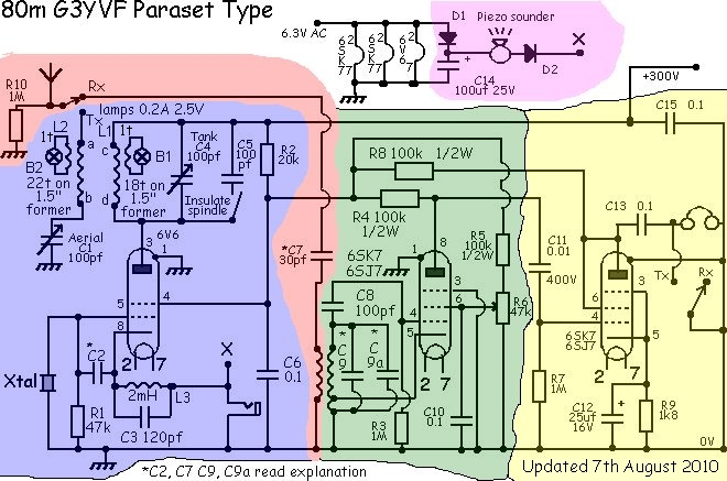
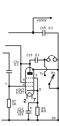
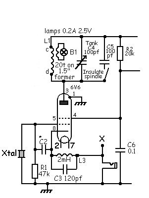
How to feed the heaters in the Paraset

First some facts. The heaters of the 6SK7 (6SJ7 if you use these) are nominally rated at 6.3v....A.C. or D.C. as it happens and draw 0.3 Amps. The heaters of the 6v6 are also rated at 6.3v....A.C. or D.C. but this time the current drawn is 0.45Amps. This valve is beam tetrode and can work hard but to do this the heaters are larger and therefore take more current.

The easiest way to run the heaters is to feed them with the correct voltage. Most mains transformers for valved equipment have a 6.3v A.C. winding just for the heaters. If your Paraset is using a 6v automobile battery to run a vibrator power pack then of course the heaters will be directly connected to the battery and therefore be operating at 6v D.C. The total heater current then required is 0.3 + 0.3 + 0.45 amps which is 1.05Amps total.

If you wish to operate your Paraset from a 12v automobile battery (which of course are more common than a 6v ones these days) then you must use electronic trickery to obtain the correct heater voltages for the valves. There are a few ways of doing this.....

Method 1

Use a resistor to drop the excess battery voltage. This is simple, effective and totally reliable IF you use a resistor that is big enough to get hot (because it will) and not break. If your battery is a 12v one, then one could expect to see approx 12.6v at its terminals (varies with the charge) and valve makers know this.

The total voltage to be lost across the resistor is 12.6 (battery volts) - 6.3 (heater volts needed) = 6.3volts. We need a resistor that with 1.05 amps flowing through it causes this voltage drop.

Ohm's Law tells us that the Voltage (6.3) divided by the current (1.05) gives us the value of resistance required, which will of course be 6 ohms.

The current squared multiplied by this resistance gives us the power dissipated in the resistor and this works out to be 6.615 watts. Use the nearest preferred value resistor you can find and make it a 10W rating. Better still make it the type that bolts down to the chassis (inside your power supply) and the chassis can be used as the heat sink. Job done. This will work for ever and should be a case of "fit and forget".

Method 2

Buy a large 5 amp regulator, the type that looks like a big power transistor. Make it a 5 amp one, as the switch on surge of cold heaters demands a lot of current that could wipe out a lesser current regulator. You can use a standard 5v one (they are cheap and plentiful) but of course you will need to raise the output voltage from 5 to 6.3. This is easy. These regulators have three connections. Power in, earth and power out. In the earth lead connect two diodes ( connect them so they point towards earth if drawn) such as 1N4001 or 4002 etc and the slight forward voltage drop across these two diodes will add up to approx 1.3v.....which is just what you need to raise the output voltage to about 6.3. Job done. This should work nearly for ever....I don't know what the life expectancy of one of these regulators is but it is a long time. Long enough for you get bored!

Method 3

More complicated this one. Connect the two 6SK7 valve heaters in parallel and then connect them is series with the heaters of the 6V6. Now the total voltage needed to power the heaters is 6.3v + 6.3v which is of course the 12.6v of your battery. HOWEVER the current distribution is not correct and MUST be corrected or the 6V6 will be damaged. Two 6SK7 will need 0.6 Amps current and one 6V6 will only pass 0.45 Amps safely. We need to make the 6V6 pass another 0.15 Amps to even things up. Using Ohms Law again we will find that 6.3 Volts divided by 0.15 Amps needs a resistor of 42 ohms. Its power rating must be 6.3 x 0.15 = 0.94 watts. So use the nearest preferred value and make a 2w resistor to be on the safe side. Connect this resistor across the 6V6 heater connections (at the valve base) and now your heaters will run from the 12v supply. This should last for ever.