|
|
|
|
|
The KK6XK Paraset Project |
|
|
I was looking for a Winter project and first learned about these rigs from the Italian website http://www.qsl.net/ ik0moz/paraset, but soon found out there were a number of resources available on their design and construction, most notably, http://www.paraset.co.uk While we all start out wanting to make something close to original, for my first one, I wanted something completely functional and to be able to use parts I had on hand. And, I had a number of design changes I wanted to try out. Apparently, most people who make one end up making several different versions and once you get the first one to work, the rest come much easier. |
|
|
|
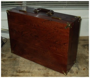
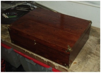
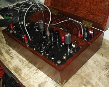
We heard that at least some of these devices came in wooden cases, so some scrap lumber and used oak flooring for the distressed look made a handy way to keep all the pieces together and make an easy package to transport to the field. |
Another view of the device in its case. The lid has separating hinges so it can be taken off and set aside, and some brass corners from an earlier project were added for protection.. Since the weight is centered on the bottom the carrying handle is on the opposite side. |
|
|
|
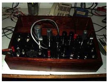
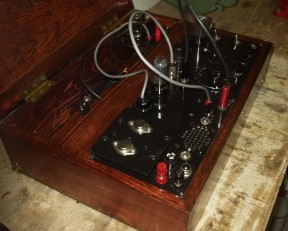
Inside view. We intentionally departed from the original by placing the power supply permanently mounted on an adjoining chassis as opposed to having standalone units. Also, we added a 6BH6 valve crystal spotter for checking crystal activity and spotting receive settings, which plugs into the power supply just to the left of the 6V6 audio tube. The spotter output cable (with the red RCA plug) need not be connected to get a strong signal. Still plenty of room for valve storage, cables, key and so forth and the lid closes over everything but the valves, which each have a PVC storage sleeve on the left site of the compartment. The headphone connection is still available- it plugs in where expected and the audio PA can get shut off. 12V power comes in the two binding posts on the lower left of the PSU and the current draw is only a couple of amps. |
Left hand view of the unit: |
|
|
|
And a right hand view of the unit: |
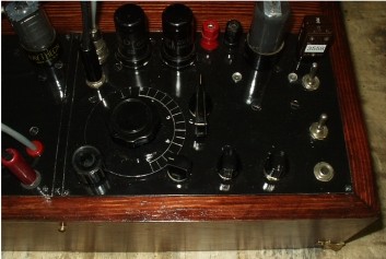
Closeup of the receiver- transmitter unit: |
|
|
|
|
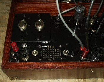
And a closeup of the PSU / audio amp side: |
|
|
|
The major feature I added was an audio amplifier and speaker. This was simply because I don’t have any high impedance headphones. And the lack of any sort of volume control in the original design wasn’t too appealing either. So instead of just one 6V6, I got two, and use the extra to drive a speaker when receiving, and in both receiving and transmitting, serve as ballast for the other 6V6 tube. Since another desire was to have this run completely on 12 volts, that made good design sense. The main unit is here: Some other deviations from the original design included the following: -both PA tuning capacitors are at DC (panel) ground. That simply makes sense for safety. -dual crystal socket for fast frequency/ band switching -no built in key. Did not look comfortable at all
|
|
-no rim drive for tuning. We added a very small band spread trimmer which works great and not having the rim drive makes it easy to spin from the 80M end to the 40M end. -for the most part, we used the design from the paraset.co.uk website, although kept the inductor and screen decoupler for the first audio amplifier. Neither is actually required. No idea where you would even find a 36 H choke, anyway, -the transmit uses the RF choke in the keying line and no gimmick capacitor. Seems to work more reliably. -The PA capacitors were porcelain 250pF units out of an old antenna tuner. Seem to work OK. -The receiver tuning capacitor was an 365pF broadcast band model with ball bearings. I simply cut out most of the rotor plates till it measured out to 100pF meshed. The smaller 100pF units would certainly have saved space. -the receive antenna capacitor is now 75pF. The original was 100pF but generally felt by all to be a bit much. Some users go as low as 10pF. The website suggests somewhere around 36pF. This is something that has to be optimized and perhaps that might best be adjustable. |
|
|
|
|
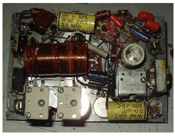
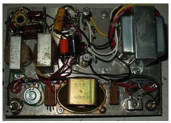
| The power supply
We decided to use the G3YVF design as it was the simplest and most straightforward, and used the least number of hard-to-find parts. The extra gear shown is for the 6V6 audio amplifier. The original unit called for a 6V vibrator. 6V as a source might be authentic, but is not available in the field, and takes a lot of current. While I had an old 12v vibrator, they are noisy, generate a lot of hash, and call for special transformers that are either simply not available or too expensive and bulky. I made several unsuccessful tries to make it work with old transformers until I was able to find the right one- a 9-0-9 transformer with a 240 volt primary from Jameco Electronics, just across the SF Bay. While only 36VA rated, it still did a great job. I also got an 8-0-8 transformer that is 56VA rated I will use for my next one. Both were very reasonably priced. |
|
Once the transformer was right, it worked perfectly and put out right around 400VDC. I tried some junk box substitutions for the 2N3055’s called for that may or may not have worked, but the actual correct parts were so inexpensive (less than $1) I got those as well. I had no 470 ohm resistors so a pair of 500 ohm units were used with no apparent ill effects, being within the tolerance levels of 470’s anyway. The regulation is another matter. Unloaded it is about 400VDC; key down and tuned is close to 300VDC. Load it much further and it saturates and starts to overheat. The buffer capacitor (also referred to as the commutation capacitor) apparently is as critical for this design as it is for a vibrator supply. I kept the original value called for (.01-600v) but some work there might help. I also tried out a bleeder resistor in series with a series of 0A2’s to partially clamp the voltage so the swing would not be so great, but I was never satisfied as to the performance. So the next one will use the heavier transformer for a start, and possibly some form of voltage regulation. I have the transistors on a separate, raised heat sink on top the panel. This was for ventilation, which proved to be unnecessary. Other issues I faced getting the rig to work included two capacitors that had simply shorted out, having sat too long in the junk box. And, the first schematic I used was wrong- there is a suppressor grid connection to the 6SK7 detector that needed to be grounded that was shown going elsewhere. It took a couple of tries to get the receive coil right. I would simply recommend winding it the right way using 22AWG- I tried using finer wire, which actually worked, but it was hard to handle and took a lot of trimming to get it right. So I decided to do it the right way. Unfortunately the only 22 AWG wire I had was bare, so some time was spent varnishing wire and hanging it out to dry it so it would work out. The transmit coil actually calls for two different size wire to be used. Mine used 16 AWG for both. It actually works pretty well- the CW produced is exactly on frequency, sounds good, and both tuning lamps go to full brilliance although I get more power on 40M than 80M. Receive is very clear and really performs well on AM transmissions- there is plenty of volume to fill the room. The antenna is a G5RV coax fed across the A and G posts. Since the tuner is built in, getting a match is simple. As pictured, I made a wooden case for it and the main unit and power supply slip in the bottom, leaving a compartment above for keys, crystals, and other accessories. I am working on the lid and unfortunately that nice filter cap sticking out of the psu unit is going to have to go, or the lid won’t close. That is what happens when you engineer-as-you-go and use what you have. Special thanks to Geoff, G3YVF, who helped me get this project going. |
|
|
|