| G3YVF's replica paraset
was tested by G3ROO, Ian Keyser, on a spectrum analyser. Des (who is making
a replica) wanted to know about harmonics and if filters would be needed
on a paraset? So what better way than to test one and see! |
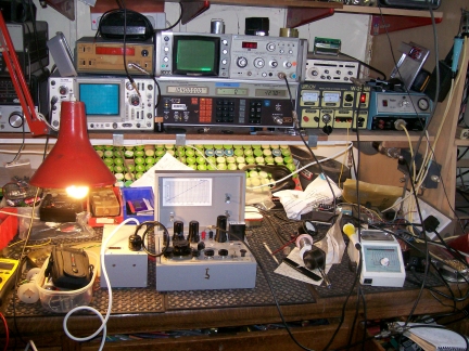 |
This photograph shows the test bench
with the paraset on transmit. Both bulbs glowing well! The other two photographs
show the screen of the spectrum analyser. The analyser has to be carefully
used to ensure it was not overloaded and reading correctly. Ian knows how
to use this test equipment and so the results can be relied upon. And how
well did it perform? |
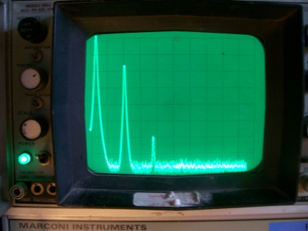 |
On 3.5MHz, fully loaded using the
light bulbs, 10dB per div of the graticule scale, you can see the 2nd. harmonic
at lower than 43dB down.
|
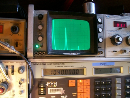 |
On 7MHz, fully loaded, again using
the light bulbs, same scale, the 2nd harmonic is lower than 50dB down, ....a
nice surprise. |
| These are figures for Geoff's
paraset. Ian's paraset didn't perform quite as well with figures that were
slightly worse. This was put down to the tank coil construction in Geoff's
paraset having a better Q than Ian's. It was also noted that small tuning
control adjustments on the paraset shifted these figures up and down a few
dB. However it was decided the figures quoted above will be typical of your
paraset.
What does it mean? The paraset is a good
performer! Output filters are not needed. |
|
|
|
|