Home Page
Advanced
The Advanced Course requires a bit more mathematics, although nothing too difficult.
Units
Most of the common prefexes were introduced in the Intermediate Course, the last few just need to be added in:
Giga (G) = * 1000,000,000
Mega (M) = * 1000,000
kilo (k) = * 1000
milli (m) = 1/1000th
micro (μ) = 1/1000,000th
nano (n) = 1/1000,000,000th
pico (p) = 1/1000,000,000,000th
Power Calculations
You were introduced to ohms law (V=IR) and the power calculation (P=VI) at foundation level, using substitution the power formula can be written differently:
P=VI, substituting V=IR into the equation gives P = IR * I, this is normally written:
P = I2R
P=VI, substituting I=V/R into the equation gives P = V * V/R, this is normally written:
P = V2/R
Series/Parallel Resistors
Resistor Symbol:
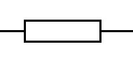
Old Resistor Symbol:

When constructing circuits, it is often the case that you don't have the exact value that is needed and so by connecting components in series or parallel you can get the value required.
Firstly dealing with resistors, if you connect two resistors in series you simply need to add the values together.
With parallel resistors you use the formula as follows:
1/R = 1/R1 + 1/R2 + 1/R3 .......
So for two resistors of 5600 ohms this gives 1/R = 1/5600 + 1/5600
Which then becomes 1/R = 2/5600
To get R you can transpose it to give:
R/1 = 5600/2 which can be written as R = 5600/2 OR 2800 OHMS
So if you have two resistors of the same value in parallel the total value becomes half of one of the original values.
As long as the values are the same this also works for 3 in parallel giving 1/3 of one of the original values etc.
The formula can be adapted to give the result for two resistors:
1/R = 1/R1 + 1/R2 = (R2 + R1)/(R1 * R2)
To get R this is than transposed to give:
R = (R1 * R2) / (R1 + R2)
Either this can be used or you can add the resistors using the standard formula:
1/R = 1/R1 + 1/R2 + 1/R3 .......
So for a 560 ohm resistor in parallel with a 360 ohm resistor in parallel with a 56 ohm resistor:
1/R = 1/560 + 1/360 + 1/56 = 1/560 + 1/360 + 10/560
1/R = 11/560 + 1/360 = ((11*360)+ (1*560)) / (560 * 360)
1/R = (3960 + 560) / 201600 = 4520 / 201600 = 452/20160 = 226/10080 = 113/5040
So R = 5040/113 = 44.6 Ohms
Potential Dividers
Using two resistors in series between the positive supply and ground it is possible to Divide the voltage using two resistors, this is called a potential divider.
The voltage at the centre point is proportional to the two resistor values and is given by:
Vout=Vin * R2 / (R1 + R2)
So if you have a 9V supply and want to produce 3V using a potential divider, if R2=4K7 what does R1 need to be.
Firstly we need to transpose the formula:
VoutR1 + VoutR2 = Vin * R2
VoutR1 = Vin * R2 - VoutR2
R1 = (Vin * R2 - VoutR2) / Vout
R1 = (9 * 4700 - 3 * 4700) / 3 = (42300 - 14100)/3 = 28200/3 = 9400 ohms
In the above example you could probably work out that R1 needed double the value of R2, but it won't always be so obvious and so you can then use the formula to do the calculation.
Capacitors
Capacitor Symbol:

Capacitors are made up of conductive plates separated by a dielectric (insulator), the formula to calculate the capacitance is as follows:
C = kA/d where k = ε0εr
C is the capacitance in Farads
k is the dielectric constant
ε0 is the electric constant (8.854*10-12Fm-1)
εr is the permittivity of the material relative to a vacuum (dry air is 1.000536)
A is the area of the overlap of the two plates in square metres
d is the distance between the plates in metres
You need to be aware of and understand the above formula
Time Constant
The time to charge a capacitor up to 63% is defined by the formula:
T = CR
This is also the time it takes to discharge to 37%
Series/Parallel Capacitors
Adding Capacitors together is the exact opposite of what you do with resistors:
Capacitors in Parallel are just added together to give a total value.
Capacitors in Series use the formula:
1/C = 1/C1 + 1/C2 + 1/C3 .......
Inductors
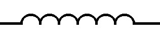
Inductor Symbol:
Series/Parallel Inductors
Series and Parallel Inductors can be added together the same way as resistors are added.
Reactance
When capacitors and inductors are used in radio circuits the reactance can be calculated as follows
XL = 2πfL
XC = 1/(2πfC)
Impedance
Impedance is the combination of reactance and resistance and because the voltage and current are in phase for resistors and 90 degrees out of phase for reactance adding the two is slightly more complicated
For series connected RC or RL circuits:
|Z| = squareroot(R2 + X2)
The Impedace will also have a phase angle which can be calculated using:
tanθ = X / R
to get θ you use the tan-1 button on your calculator.
The voltage across the Resistance and Reactance can be calculated in a similar manner:
|VZ| = squareroot(VR2 + VX2)
Resonance
For resonance XC = XL
The formula for calculating resonant frequency is as follows:
f = 1 / [2* π * squareroot(L * C)]
Transposition of the resonant frequency formulaThe resonant frequency of a circuit is given as:
f = 1 / (2π * squareroot(L * C))
you will need to be able to transpose this to calculate C or L:
squareroot(L * C) = 1/(2πf)
LC = (1/2πf)2
C = [(1/2πf)2]/L or L = [(1/2πf)2]/C
you will only be given:
f = 1 / (2π * squareroot(L * C))
so if you struggle to transpose the formula you will need to memorise the transposed forms.
The Q of a circuit
The Magnification factor Q, or Quality of a series tuned circuit can be worked out by looking at the current (I) flowing through the circuit at resonance, which will consist of the source voltage e.g. 100mV divided by the series resistance e.g. 100R (because the L and C will cancel each other out) which in this case would be 100mV/100R = 1mA.
At resonance the impedance of the L (XL) or C (XC) can be calculated e.g. if Xc = XL = 1000, you multiply this impedance by the current (I) it will give you 1mA * 1000R = 1V which is 10 times the source Voltage (100mV). So in this case The Magnification factor Q = 10.
The Q of a circuit can also be caluculated by measuring the bandwith at the half power point (0.707 of the voltage), then applying the formula:
Q = fc/(fu - fl) = centre frequency / bandwidth
Another method of calculating Q is to use the formula:
Q = 2πfL/R or 1/(2πfCR)
For a parallel tuned circuit the AC Resistance is at a maximum at Resonance, this resistance is called the Dynamic resistance, RD it can be calculated as follows:
RD = L/CR
The value of Q can also be worked out using RD:
Q=2πfCRD
Damping resistors can be used to reduce the likelyhood of a tuned circuit oscillating, adding in damping resistors will however reduce the Q.
Quarter Wave Impedance Transformer
A quarter wave length of transmission line can be used as an Impedance Transformer, the impedance of the transmission line Zo required can be calculated using the following:
Zo2 = Zin * Zout
So if you want to connect 50 ohm impedance (Zin) to a 100 ohm load (Zout) you will need to calculate the impedance of the quarter wave transmission line:
Zo2 = 50 * 100 = 5000
Zo = 70.7 ohms
Therefore if you connect a quarter wave of 70.7 ohm transmission line between the 50 ohm feeder and the 100 ohm load you shouldn't get a mismach.
Field Strength Calculation
To calculate the field strength around your antenna you first need to work out the erp:
erp = power * gain (linear)
Therefore if directly in front of your antenna you have a gain of 3dbd (relative to a dipole) you will have double the power in that direction. So in this situation if you are transmitting 8W the erp would be 2 * 8W = 16W
To calculate the Field Strength E you can then use the formula:
E = [7 * squareroot(erp)]/d
So at a distance of 2 metres in front of the antenna mentioned above the 16W erp becomes an Electric Field Strength of:
E = [7 * squareroot(16)]/2
E = [7 * 4]/2
E = 28/2 = 14 Volts per Metre
Transformers
Transformer Symbol:
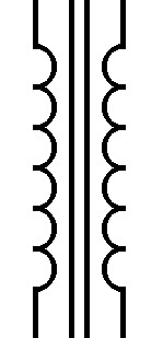
An AC current in a coil produces an alternating magnetic field and if it is adjacent to another coil an AC current will be induced in the second coil, this effect is called mutual inductance
Ignoring losses the ratio of the Primary to the Secondary of a transformer determines the Output voltage related to the input:
Vs=VP * Ns/Np
The current is inversely proportional:
IP=IS * Ns/Np
and the impedance ratio for a transformer is as follows:
ZP=ZS * (Np/Ns)2
Eddy currents are loops of induced current which you can get in the cores of transformers producing heating and decreasing the efficiency. They can be reduced by using either a laminated or ferrite core
PLL (Phase Lock Loops)
PLLs are used to produce discrete frequencies in radios, they use a phase comparator to compare a divided down (divided by A) reference clock (fcrystal)with the output of a Voltage Controlled Oscillator (VCO) (fout) divided by a programmable divider (divide by N) and use the comparator output to adjust the VCO frequency.
When using a PLL you would apply the formula:
Fout = (fcrystal * N)/A
and
fstep = fcrystal / A
FM Modulation
FM Modulation is where the carrier frequency is altered by an amount proportional to the amplitude of the applied (AF) audio signal. The deviation (Δf) is how much the carrier varies when the modulated signal is applied.
Carson's rule
Theoretically a carrier that is Frequency Modulated by a broad spectrum of frequencies (eg. Audio) has infinite bandwidth, however 98% of the bandwidth of the signal can be calculated by using the formula below:
bw = 2(AFmax + Δf)
VSWR (Voltage Standing Wave Ratio)
When you connect a radio to an antenna via some coax, if there is an impedance mismatch, then when you transmit some of the AC voltage will get reflected back down the coax. The interaction between the forward standing wave Voltage (Vf) and the reflected standing wave Voltage (Vr) can produce unacceptable feed point impedances which can damage your radio and are therefore to be avoided.
The VSWR can be calulated using the formula below:
SWR = Vmax/Vmin = (Vf + Vr) / (Vf - Vr)
Diodes
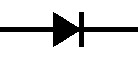
Diode Symbol:
A conductor is material where each atom has a surplus of electrons which can easily be encouraged to move from one atom to the next.
Using a battery connected to a conductor, the electrons flow from the cathode (-ve) to the anode (+ve), this is the opposite way to how conventional current is viewed, therefore what is normally described is hole flow (the flow of the gaps left by the electrons flowing in the opposite direction).
By treating silicon it can be made to either have an excess of electrons, or a deficit.
silicon treated to have an excess of electrons is described as having been negatively doped (n) and silicon treated to have a deficit is described as having been positively doped (p).
If you join some p doped silicon to n doped silicon you will get a pn junction and the electrons will easily flow across that junction from the n doped material to the p doped material, but not very easily in the opposite direction. This configuration is called a diode and even in the forward direction you will still need around 0.7V to get the current to flow.
The direction of the arrow in the diode symbol is the direction conventional current will flow easily.
BJTs (Bipolar Junction Transistors)
Transistor Symbol:
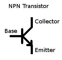
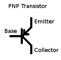
A Bipolar Junction Transistor consists of either doped silicon in an npn configuration or pnp configuration.
With the pnp transistor the electrons will flow across the base-emitter (np) junction [like a diode](in the opposite direction of the arrow on the transistor symbol), but not want to flow across the collector-base (pn) junction [like a diode], by supplying extra electrons to the base (n) you can overcome the reverse biased collector-base (pn) diode junction and allow current to flow from the collector to the emitter.
Using convention current flow (hole flow) current flows into the base of an npn transistor to the emitter, allowing a proportionally greater current to flow from the collector to the emitter, this is the transistor's current gain β.
Radios often have a PTT (Push To Talk) output which can be used to drive other circuits, the circuit which is often used is an open collector NPN transistor. The one below is from the FT897D schematic diagram:
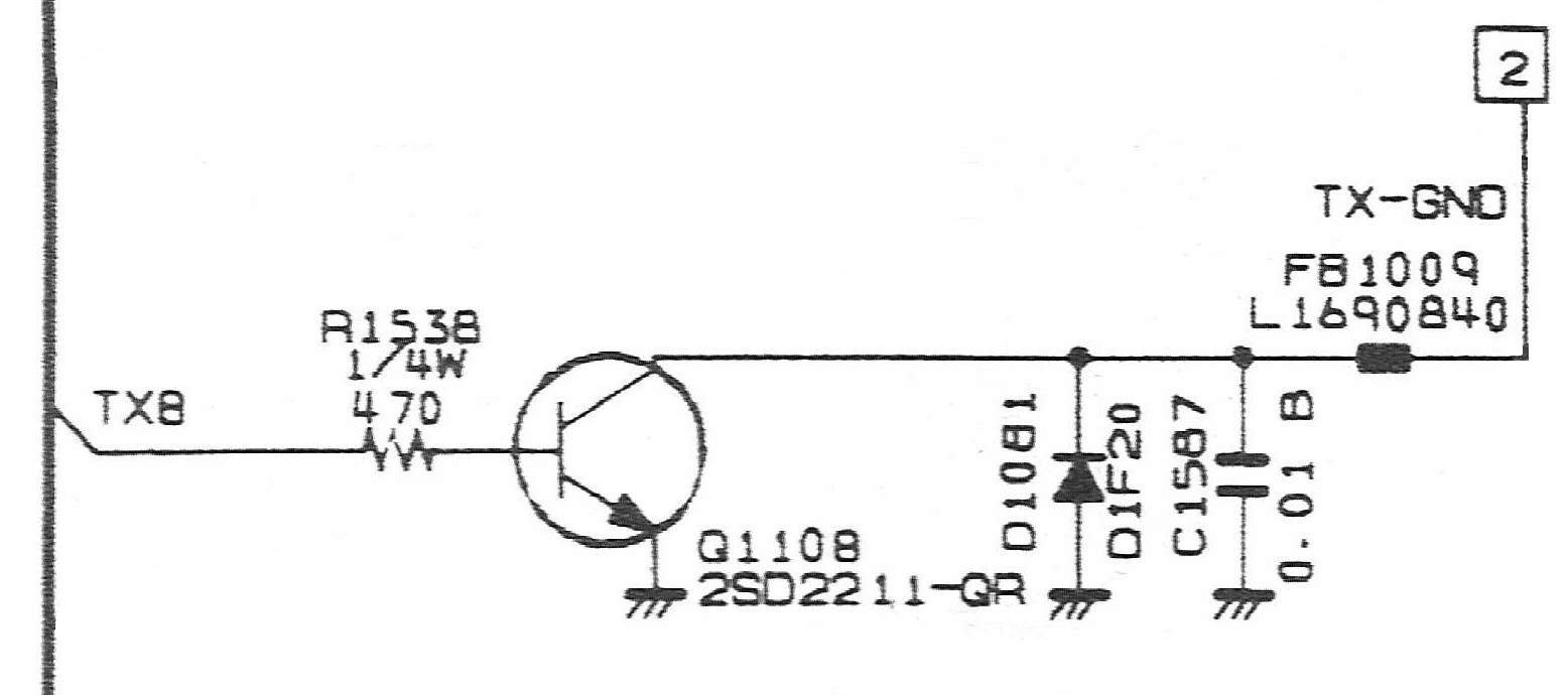
The transistor used is a 2SD2211 and by looking at the datasheet for that transistor, one can find the transistor's β, DC current transfer ratio, current gain or hfe (all the same thing), in this case using test conditions of Vcc = 5V AND Ic=0.1A it is specified as having a minimum β of 120 and a maximum of 390.
When PTT is enabled the transistor is being fed 5V, through the 470 ohm resistor and then through what is effectively a diode (pn junction of the transistor), so to calculate the current into the base of the transistor Ib you need to subtract 0.7V (for the base-emitter voltage drop) from 5V to give 4.3V across the 470 ohm resistor.
As V=IR and I=V/R you can calculate the base current Ib:
Ib = 4.3V / 470 = 0.00915 Amps
This would normally be written as 9.15 mA
To work out that the gain of the transistor is enough to switch on an output relay you would use the minimum β value from the data sheet and multiply it by the base current Ib to give the collector current Ic:
Ic = β * Ib = 120 * 9.15mA = 1.10 Amps
The output of the transistor (collector) is connected to a reverse biased diode to earth, the reason for this is so that if you connect the output to an inductive load (e.g. a relay) when you turn the transistor off you can get a large negative voltage which would damage the transistor if the diode wasn't there to keep the negative voltage down to around -0.7V.
There is also a capacitor (0.01μF) and an EMI Suppression Filter inductor BLM21P300SPT (30 ohms impedance, 0.015 ohms DC resistance, max current = 3 Amps) to limit any rf being fed back into the radio from external circuits.
Although the transistor has a maximum Ic of 1.5 Amps and we worked out Ic would be at least 1.10 Amps and the EMI Suppression Filter is rated at 3 Amps the FT897D manual specifies that the output is only rated to drive a relay coil with a current of up to 400mA. This may be due to the width of the tracks on the printed circuit board.
The Ic we worked out was based on the minimum β and normally it isn't a good idea to rely on the gain of the transistor to ensure that you don't exceed the maximum collector current of the device (make sure the load resistor at the collector is enough to keep the current down).
In this situation if you are using a Voltage supply of 13.8V and the maximum current allowed is 400mA, the saturation voltage (collector emitter voltage) for a BJT is around 0.2V, so 13.8V - 0.2V = 13.6V.
V/I = R = 13.6V/0.4A = 34 ohms
Therefore the minimum load resistance the output can drive is 34 ohms.
Power Levels (dB)
RF power gain/loss in normally measured in decibels, and is defined by the following formula:
Gain (loss) = 10log10(Power out/Power in) dB
So if your amplifier has an input of 1W and an output of 10W you can work out the gain in dB as follows:
Gain (loss) = 10log10(10/1) dB = 10log10(10) dB = 10 * 1 dB = 10dB
If you measured the voltage on the input and the output of your amplifier as you know the input and output impedance this gives:
Gain (loss) = 10log10(Vout2 / Rout) / (Vin2 / Rin)
If Rin = Rout you can cancel out the two resistors giving:
Gain (loss) = 10log10(Vout2) / (Vin2)
One of the standard properties of logarithms is that:
10log10(a2/b2 = 20log10(a/b)
Therefore the gain can be re-written as:
Gain (loss) = 20log10(Vout) / Vin)
When using Decibels for RF Power it is assumed that the input and output impedance are the same.
Antenna Gain (dB)
When quoting the gain of a Yagi Antenna you would normally use dBd, which is gain relative to a dipole (in dB), the formula to work it out is as follows:
Gain = 10Log10(power from Yagi)/(power from dipole) dBd
Return Loss (dB)
The Return Loss is related to the SWR in that the lower (better) the SWR, the higher the Return Loss, Return loss is calculated as follows:
Return Loss = 10log10(Reflected power / Incident power) dB
Incident power is sometimes called Forward power
Velocity Factor
The velocity of light in a vacuum (c) is 299, 792, 458 m/s, the speed of a radio wave in a vacuum is the same. However radio signals travel at a slower speed through conductors and the ratio between the velocity of light and the speed radio signals travel through a specific conductor is called the Velocity factor (VF), this can be written as follows:
v = VF * c
To make calculations easier it is normal to round c up to 300,000,000 m/s
The wavelength of a radio wave is related to its Frequency by the formula:
v = fλ
where v is the velocity of the radio wave, usually between 0.5 and 1.0 times the speed of light, f is the frequency and λ is the wavelength.
Using v = 300,000,000 m/s, so at 145,375,000 Hz (145.375MHz) the wavelength λ can be calculated as follows:
λ = v/f = 300,000,000 / 145,375,000 = 2.064 metres
You may note that this is very close to 2 metres which is why 145.375MHz is described as being in the 2 metre frequency band.
The period of the waveform can also be calculated using the formula:
T = 1/f
Where T is in Seconds and f is in Hz.
PSU Voltages
When designing power supplies you need to be aware that mains voltage is rms, and you need to use peak voltage when calculating maximum voltage levels and the DC output after rectification and smoothing. The RMS (Root Mean Squared) Voltage is related to the peak voltage using the formula:
Vrms = Vpeak / 1.414
The number 1.414 is actually the square root of 2, but for most calculations 1.414 will do.
So using a 230V in 15V out transformer your output (with no load) will be 15V RMS, you will need to calculate the DC voltage, so that you can calculate the voltage rating of your power supply components:
Vpeak = 15V * 1.414 = 21.21V
So after smoothing you will have 21.21V, although you will probably lose around 10% under full load conditions, which is the reason for using a regulated power supply rather than just a transformer, rectifier and smoothing capacitor.
73 Trev (G7PVS)
Last modified: July 07 2017 15:22:34.