Home Page
Intermediate
The Intermediate Course requires a bit more mathematics, although nothing too difficult.
Units
A few prefexes were introduced in the Foundation Course, you will need to learn a few more at the Intermediate level:
milli (m) = 1/1000th
micro (μ) = 1/1000,000th
nano (n) = 1/1000,000,000th
pico (p) = 1/1000,000,000,000th
nano and pico are often used when referring to capacitors i.e 10pF meaning 10 picofarads
Capacitors are a circuit element used to store energy (measured in Farads)
Series/Parallel Components
When constructing circuits, it is often the case that you don't have the exact value that is needed and so by connecting components in series or parallel you can get the value required.
Firstly dealing with resistors, if you connect two resistors in series you simply need to add the values together as follows:
If you have calculated the value you want as being 7200 ohms you could make this up using the preferred values of 3600 ohms and 3600 ohms (or alternatively 1600 and 5600) which when added together and wired in series gives 7200 ohms.
If you have calculated the value you want as being 2800 ohms you can make this up by using two of the preferred 5600 ohms in parallel as the formula for calculating parallel resistors is as follows:
1/R = 1/R1 + 1/R2 + 1/R3 .......
So for two resistors of 5600 ohms this gives 1/R = 1/5600 + 1/5600
Which then becomes 1/R = 2/5600
To get R you can transpose it to give:
R/1 = 5600/2 which can be written as R = 5600/2 OR 2800 OHMS
So if you have two resistors of the same value in parallel the total value becomes half of one of the original values.
As long as the values are the same this also works for 3 in parallel giving 1/3 of one of the original values etc.
You don't need to know how to add different values in parallel until you move onto the Advanced Course.
Kirchoff's Laws
Kirchoff's 1st Law
Kirchoff's 1st Law states that the sum of all currents flowing into and out of a node is zero.
Kirchoff's 2nd Law
Kirchoff's 2nd Law states that in any closed loop the sum of all voltages is zero.
These two laws can be used to work out the voltages and currents in circuits with multiple sources and branches.
An example (borrowed from Wikipedia)
Given the following circuit:
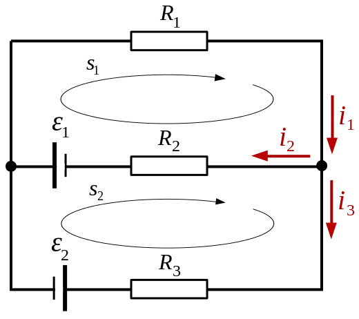
Using Kirchoff's 1st law the sum of the currents in the node on the right are added up, the arrows pointing towards the node are positive and the arrows pointing awary are negative.
This gives the following:
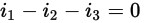 Equation 1
The next thing is to apply Kirchoff's 2nd law, so using the direction of the arrows as a positive direction and voltage sources which drive current in that direction as positive and voltage drops across resistors as negative you get:
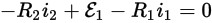 Equation 2
With the second loop (s2) the voltage sources are negative as they are in the opposite direction to the direction of the loop (s2). As i2 is in the opposite direction to the direction of the loop (s2) and the voltages across resistors are subtracted you get a negative of a negative or a positive for R2i2. This is shown below:
 Equation 3
To solve this you need to reduce the unknowns by substitution so you can write Equation 1 in terms of i3 and substitute it into Equation 3 to get rid of i3
i3 = i1 - i2 Equation 4
-R3(i1 - i2) - E2 - E1 + R2i2 = 0 Equation 5
If you now write Equation 2 in terms of i1 that can be substituted into Equation 5 to get rid of i1, leaving i2 as the only unknown.
i1 = (E1 - R2i2)/R1 Equation 6
-R3i1 + i2R3 - E2 - E1 + R2i2 = 0
-R3((E1 -R2i2)/R1) + i2R3 -E2 - E1 + R2i2 = 0
Multiplied out:
-R3E1/R1 + R3R2i2/R1 + i2R3 -E2 - E1 + R2i2 = 0
In terms of i2:
i2(R2 +R3 + (R2R3)/R1) = E1 + E2 + (R3E1)/R1
i2 = (E1 + E2 + (R3E1)/R1) / (R2 + R3 + (R2R3)/R1)
For this example R1=100, R2=200, R3=300, E1=3V and E2=4V
These values can now be inserted into the equation
i2 = (3 + 4 + (300*3)/100) / (200 + 300 + (200*300)/100)
i2 = (7 + 900/100) / (500 + 200*3)
i2 = 16 / 1100 = 8 / 550 = 4 / 275 Amps
Using Equation 6:
i1 = (E1 - R2i2)/R1
i1 = (3 - 200*(4/275)) / 100
i1 = ( (825 - 800)/275 ) / 100
i1 = (25/275)/100
i1 = (1/11)/100 = 1/1100 Amps
Using Equation 4
i3 = i1 - i2
i3 = 1/1100 - 16/1100
i3 = -15/1100 = -3/220 Amps
This shows that the direction of the i3 arrow is backwards with respect to the actual current flow.
Power loss in Feeder
In a 50 ohm system a 3dB loss means you lose 50% of the power, so 100W from your radio and 3dB loss in your coax means that you will only get 50W at your antenna.
In a 50 ohm system a 10dB loss means you lose 90% of the power, so 100W from your radio and 10db loss in your coax means that you will only get 10W at your antenna.
Whan choosing coax you can look up the loss at different frequencies usually per metre
ERP (Effective Radiated Power)
Antenna gain can be either given with respect to a point source (dBi) or with respect to a dipole (dBd)
The antenna doesn't actually amplify the signal, just concentrates the signal in certain directions
If your antenna has 3dBd of gain, if you put in 10W, you will get the same signal out in the direction you want as if you were transmitting 20W into a dipole, this is the ERP.
Wavelength Calculation
Frequency and Wavelength are related to each other by the formula below:
v = f * λ
v is the velocity of radio waves and depends upon what the radio waves are travelling through.
For the Intermediate Level the velocity (v) of radio waves will be given.
f is the frequency and λ is the wavelength.
In a vacuum v = 300,000,000 m/s, so at 145,375,000 Hz (145.375MHz) the wavelength λ can be calculated as follows:
λ = v/f = 300,000,000 / 145,375,000 = 2.064 metres
You may note that this is very close to 2 metres which is why 145.375MHz is described as being in the 2 metre frequency band.
73 Trev (G7PVS)
Last modified: July 07 2017 14:14:04.