Troubleshooting The Detector/AVC/1st Audio Stage


Function:

The detector stage is often referred to as the demodulator stage, or sometimes as the second detector to distinguish it from the mixer which is sometimes referred to as the first detector, a name often used in early receivers.
The detector stage discussed here uses a 6SQ7 duo-diode/triode tube and performs three separate functions. They are:

Theory of Operation:

Demodulate, or remove the audio component of the received signal - The input signal fed to the detector comes from the preceding I-F stage. This is an alternating signal composed of the carrier signal which is modulated by the audio component. The detector or demodulator section consists of the cathode (pin 3) and the two diode sections (pins 4 & 5) of the tube, which form a half-wave rectifier. The incoming signal is rectified (the lower half of the wave form is chopped off) by this circuit. Resistor R-26 and capacitor C-26 act as a filter to remove the RF component of the signal, leaving only the audio portion (see illustration).

Amplify the audio signal and pass it on to the audio output stage - This audio signal appears across the volume control R-27 where it is coupled to the grid of the triode section of the tube through coupling capacitor C-31. The amplified signal appears on the plate circuit where it is passed on to the audio output stage through coupling capacitor C-32.

Developt the AVC (automatic volume control) voltage - A negative voltage is developed across the volume control R-27 as a result of the rectification of the signal by the diode section (pins 4 &5). Resistor R-28 and capacitor C-28 filter this negative voltage and smooth it out to a DC voltage. The amount of AVC voltage developed depends on the strength of the received signal. The stronger the signal, the more voltage developed. This negative bias voltage is applied to the grids of the preceding R-F and I-F stages. When the incoming signal is strong, a high AVC voltage is developed which reduces the gain of these preceding stages. A weaker signal, develops less AVC voltage which increases the gain of these preceding stages. Thus, the AVC voltage acts to hold the gain fairly constant over a wide range of signal strengths. This keeps the audio from becoming overly loud when tuning from a weak station to a stronger one. The wire that feeds the AVC signal to the preceding stages is called the AVC bus.

Troubleshooting:

A quick check for operation of the detector stage can be made by applying a modulated signal from the signal generator to the grid of the preceding I-F stage. If the modulated tone from the signal generator is heard in the speaker, the detector and audio amplifier portions of the stage are working.
The operation of the AVC portion of the circuit can be checked by measuring the AVC voltage across the volume control potentiometer R-27. If the AVC circuit is functioning, a negative voltage will be read. By adjusting the signal strength of the signal from the generator, this voltage should vary accordingly. A stronger signal should produce more AVC voltage, and a weaker signal, less AVC voltage. Note: by design characteristics the AVC circuit can handle signal strengths only up to a certain point. If the output from the signal generator is increased beyond that point, the AVC voltage will no longer increase with increase in signal strength.

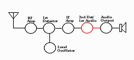
The charts below give symptoms and possible caused for the detector/AVC/audio amp circuits. Refer to the schematic diagram above.

Service Date Chart For Inoperative 1st Audio Stage
StepCheckResponsePossible cause
1Apply an audio frequency signal to plate (pin 6)Tone not heard or weakOpen coupling capacitor C-32
Tone heard in outputProceed to step 2
2Apply AF test signal to first AF grid (pin 2)Tone not heard or weakDefective tube, substitute a know good one
Missing plate voltage (R-32 open)
If grid lead is shielded, check for shorted center lead to shield
Tone heard in outputProceed to step 3
3Apply AF test signal across volume control R-27Tone not heard or weak Open coupling capacitor C-31
Open volume control
If lead to volume control arm is shielded, check for shorted center lead to shield

Service Data Chart For Other AF Stage Symptoms
SymptomAbnormal readingCheck for
Poor tone qualityFirst AF plate (pin 6) voltage lowShorted or leaking coupling capacitor C-32
Plate resistor R-32 increased in value
Voltages normalShorted or leaking coupling capacitor C-31
Incorrect value of grid resistor R-31
HumVoltages normalDefective tube, replace with known good one
Incorrect routing of grid leads
Incorrect position of coupling capacitor
MotorboatingOpen grid resistor R-31
Intermittent reception (fading)Coupling capacitors C-31 and C-32 may be open intermittently
Defective tube
Defective volume control R-27

Service Data Chart For Inoperative Detector Stage
(assume 1st audio stage is operating properly)
StepCheckResponsePossible cause
1Apply a modulated signal at the intermediate frequency to grid of preceding I-F stage. If modulation note is not heard, tune the generator either side of the intermediate frequency. The modulation is heard at an off-frequency settingThe I-F stage is out of alignment. Perform I-F alignment procedures outlined for the receiver
The modulation note is not heardProceed to step 2
2Apply the I-F test signal to the plate of the I-F tube at the intermediate frequency. Set the attenuator for full outputThe modulation note is heard in the speakerThe trouble is in the I-F stage. Refer to troubleshooting the I-F stage
The modulation note is not heardDefective tube
Open I-F transformer winding
Shorted I-F trimmer capacitor

Service Data For Other Detector Stage Symptoms
SymptomCheck for
HumDefective tube
Incorrectly dressed leads in the diode plate return circuits
If set has phono input, check for open wiring or shielding of input circuit
Weak reception and oscillationIncorrect alignment
Open AVC by-pass capacitors C-28, C-29, and C-30
Distortion on strong signalsLeaky AVC by-pass capacitors C-28, C-29, and C-30
Open resistor R-28

Typical Voltage Readings
Tube elementPin No.Volts
Plate6100-170
Grid20
Cathode30