Troubleshooting The I-F Amplifier Stage
 |
|
 |
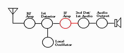
Refer to the charts below and the schematic diagram above. Assume all other
stages are functioning properly.
| Symtom | Abnormal reading | Check for |
|---|---|---|
| Inoperative | Plate voltage (pin 3) = 0 | Open
I-F transformer winding L10. Open plate resistor R-25 Shorted by-pass capacitor C-25 |
| Screen voltage (pin 4) = 0 | Open screen
dropping resistor R-24 Shorted screen by-pass capacitor C-24 | |
| Cathode voltage (pin 8) = 0 | Shorted cathode by-pass resistor C-23 | |
| High cathode voltage | Open cathode resistor R-23 | |
| All voltages normal | Defective tube Shorted trimmers in the I-F can I-F transformer secondary open Open AVC by-pass capacitor C-28 | |
| Weak signal | All voltages OK | Weak tube Open AVC by-pass capacitor C-28 Open cathode by-pass capacitor C-23 Open plate by-pass capacitor C-25 I-F circuits out of alignment |
| Noise | All other checks OK | Noisy tube Corrosion in the I-F transformer windings |
| Squeal or oscillation | All other checks OK | Open screen by-pass capacitor C-24 Improper ground of tube shield Open AVC by-pass capacitor C-28 Open plate by-pass capacitor C-25 Incorrect routing of wiring |
| Circuit | 6K7 Pin No. | Volts |
|---|---|---|
| Plate | 3 | 245 |
| Screen | 4 | 100 |
| Cathode | 8 | 8 |
| Plate lead | Blue |
| B plus lead | Red |
| Grid lead | Green |
| Grid return | Black |
   |