The field coil is often used as the filter choke of the receiver
power supply. The DC current passing through the field coil creates a strong
magnetic field to operate the speaker. Because the field coil is used as the
filter choke, it can have a high hum component. This hum component affects the
voice coil causing it to be heard in the speaker. To reduce this hum a
hum-bucking coil, consisting of a few turns of wire, is wound on the pole-piece
and stationary to the field coil. The hum-bucking coil is in series with the
voice coil and connected in such a manner that any AC component induced in
the voice coil by the field coil is out of phase with the AC component
induced in the hum-bucking coil, and the two will tend to cancel out reducing
the hum. If the hum-bucking coil leads have been disconnected and then
reconnected so that it is in phase with the voice coil, the AC component will
be reinforced and the hum level increased.
Some receivers with electromagnetic dynamic speakers may have the speaker
leads terminated in a plug, which plugs into a mating socket on the receiver
chassis.
Be sure to have this plug inserted before applying power otherwise damage to
the first electrolytic filter capacitor may occur. The reason for this is
that without the field coil in the circuit, there is no load on the output
of the rectifier tube. This no-load condition will allow the electrolytic
capacitor that is connected directly to the output of the rectifier to charge
up to the peak voltage of the high-voltage secondary, which may exceed the
maximum rated voltage of the capacitor.
If the field coil winding is defective, the speaker will no longer function
properly. The options are; repair the field coil, find another field coil
replacement speaker, or replace the speaker with a permanent magnet (pm)
type.
A quick speaker check is to pull the audio output tube with power on the receiver. When this is done, a click should be heard in the speaker. Unseating of the tube causes the B+ voltage on the plate pin of the output tube to rise, which causes a surge in the primary of the output transformer. This surge is induced in the secondary and energizes the voice coil of the speaker, producing the click. This check does not indicate how well the speaker will function, but merely that the output transformer and voice coil windings are not open. If no click is heard when performing this test, check for B+ voltage on the plate pin of the output tube socket. Missing B+ may indicate an open primary winding of the output transformer, or open field coil (see below). If B+ is present then either the output secondary or voice coil may be open.
A quick field coil check is, with power applied to the set, bring the blunt end of a piece of iron, such as a nut-driver wrench near the center pole piece. A good operating field coil will have a strong pull on the wrench. An open coil will have either no or slight attraction due to residual magnetism. If the speaker has a dust cover over the pole piece it may be difficult to bring the wrench near the pole piece and the test may be unreliable. If an open coil is suspected, check for missing B+ voltage at the electrolytic filter capacitor on the output of the field coil.
A check for continuity of the field coil with an ohm-meter can determine if the coil is open. The resistance of field coils vary and the value will usually be indicated on the receiver schematic. Ranges vary from around 800 to 2500 or so ohms. A low resistance reading would indicate a shorted coil. Sometimes a coil will short to the pole piece on which it is mounted, and if the speaker is mounted on the chassis, can cause partial or complete loss of B+ voltage
If an open coil is indicated, the problem can sometimes be where the lead goes into the coil. Try peeling back the outer layers of insulation to expose where the lead attaches to the coil wire. If that is where the break is, it can be re-soldered. If the break is inside the coil, the coil would have to be replaced.
Sometimes the construction of the speaker pot does not lend itself to the
removal of the field coil. In this case, about the only thing to do is replace
the entire speaker assembly. Rewinding a field coil can be quite a chore as
there are thousands of turns of very small gauge wire, however there are some
service providers who will rewind field coils.
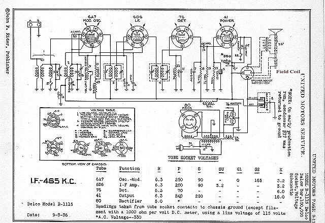
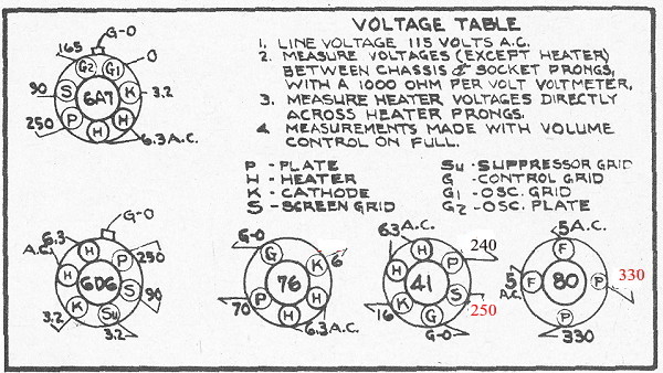
The set uses a 6A7 converter, 6D6 IF amplifier, 76 detector/1st AF amplifier,
41 output and 80 rectifier.
Looking at the schematic it can be seen that one side of the field coil
comes directly off of one of the filament pins of the 80 rectifier
and the first filter cap (A). This will be the max B+ voltage and the
voltage table shows the voltage on this pin of the 80 to be 330 vdc. The
other lead of the field coil ties to the voltage source that goes
directly to the screen grid of the 41 output tube and the second filter
cap (B). The tube socket voltage chart shows this voltage is 250 volts. This
calculates to a voltage drop across the field coil of 80 volts (330 - 250 = 80).
Now if we know the current draw through the field coil then we can calculate its
dc resistance using ohms law.
Looking the tube types up in the tube manual, gives the following current values.
Using ohms law, R=E/I = 80/.061 = 1,311 ohms.
We also have to consider that the current values given in the tube manual are typical values and actual current for each tube can vary from these values some depending upon the design of the set, so a field coil with a DC resistance somewhere in range of 1300 to 1600 ohms should work.
To replace the dynamic speaker with a pm (permanent magnet) speaker, the field coil that was serving as a filter choke must be replaced with a suitable substitute. The coil can be replaced with either a regular filter choke, which is mounted on the chassis and simply soldered in place of the now missing field coil, or a power resistor that matches the resistance of the field coil can be used. The use of a resistor will reduce the filtering of the B+ as a resistor has no inductance, so extra filter capacitance may have to be added to keep the hum within acceptable limits. Consideration must also be given to the power rating of the resistor. Wattage can be calculated by squaring the current flowing through the resistor, multiplied by the resistance.
Example: assume a 1500 ohm resistor used to replace a field coil has 70 milliamperes of B+ current flowing through it. Squaring the current, (.07 X .07 =.0049), multiplied by 1500 ohms = 7.35 watts. At least a 10 watt unit should be used, and 15 watts would be even better. Since this resistor will run rather warm it should be mounted so the heat generated will not affect other components.
With the field coil replaced by either a resistor or filter choke, a pm
speaker can now be used to replace the dynamic one. If the output transformer
is mounted on the dynamic speaker, it must be removed and either mounted on
the replacement speaker or on the chassis and wired to the new speaker.
See diagram of electromagnetic dynamic field coil speaker with hum-bucking coil, a typical power supply circuit with speaker field coil used as filter choke, and diagrams showing the R.M.A speaker- plug wiring.