RESTORATION
TIPS, HINTS,
& KINKS
INDEX
- Troubleshooting the stages of a superheterodyne
receiver
- Function, theory of operation, schematic diagrams, and troubleshooting
charts for the different stages of a typical superheterodyne receiver. Covers
the RF amplifier, converter, intermediate frequency, detector/avc/1st audio,
audio output stages, plus the AC and vibrator power supplys, and the electron-ray
tube (tuning eye) circuit.
Charts give symptoms and possible cause.
- Determining Turns Ratio and Impedance Ratio of
Output Transformers
- An easy method to determine the turns ratio and impedance of
an unknown output transformer for replacement in your set.
- A Guide to Zenith Model Numbers
A guide to help identify cabinet style, chassis type, and model year from
the model number of the Zenith
Black Dial Era (1936-1949) sets,
by Blake Deitze.
- Checking Signal Generator Calibration
How to calibrate your signal generator using stations on the broadcast band
- Rider's Manuals By Years Covered
The approximate years covered by the Rider's
manuals for volumns 1 thourgh 19.
- Rebuilding Philco Block Capacitors
Information at Chuck Schwark's website on rebuilding Philco Bakelite block
capacitors
- Cleaning Tuning Capacitors
- Molded Mica Capacitor Color Codes
- How to read the color code on molded mica capacitors
- Resistor Color Codes
- How to read the color codes on resistors, including the early styles where the body is one
color, the end another, and a dot or band in the center, and the flexible types.
Also find out why manufacturers used odd resistance values such as, 51,000 ohms instead
of 50,000 - 99,000 ohms instead of 100,000 ect.
- Ohms Law Chart
- A handy chart for determining the formulas for Current, Resistance, Voltage, and Power.
- Ballast Tube and Plug-in Resistor Codes
- How to read the RMA codes on ballast tubes and plug-in resistors along
with type of dial lamp used with each. Chart of dial lamp data. A brief
history of the development of the ballast tube and plug-in resistors with
diagrams of ballast circuits.
- Dial Lamp Data Chart
- Dial lamp data
- Identifying Power Transformer Windings
- How to identify the various windings on power transformers
- Speaker Repair
- Tips on repairing speakers, centering cones, ect.
- Electromagnetic Dynamic Speakers
- Explaination of the workings of electromagnetic dynamic speakers with
diagrams. Checking for proper operation. Replacing dynamic speakers. Determining
the DC resistane of field coils. Diagrams showing RMA speaker plug wiring.
- Repairing I-F Transformers
Excellent article in Antique Radio Classified
on repairing I-F
transformers
- Troubleshooting
Troubleshooting tips
- A Replacement For The 1L6 In Zenith Trans-Oceanics
Fred Gordon explains how to replace the 1L6 with a 1LA6
- Battery Cable Lead Color Codes
Standare RMA color codes use in cables for battey sets
Checking Signal Generator Calibration
When aligning a receiver, it is important that the frequency dial of the
signal generator be accurately calibrated. This is to assure that you align
the I-F and R-F circuits to the frequencies as specified in the alignment
procedures. It is not necessary to check the calibration of the generator
at all points of the dial, as there are just a few test frequencies that are
use in the alignment of most receivers. These include several I-F frequencies,
and a few points in the broadcast band.
A quick and accurate check of the calibration would be to use a frequency
counter which would give a direct readout of the generator frequency. Most
generators have adjustments that allow the frequency to be shifted, so it
would just be a matter of setting the dial on the frequency to be checked
and then adjusting either the coil or trimmer capacitor to make the frequency
agree with the dial setting.
Lacking a frequency counter, there are other ways to check the calibration.
Stations on the broadcast band maintain their frequency to very close
tolerances, and we can use these stations on known frequencies to check
the generator.
Lets see how we go about making the check suggested above. Tune a receiver
in to a station of known frequency on the low end of the broadcast band,
somewhere around 600 kHz. Lets say we have one at 610 kHz. Connect the output
of the signal generator to the antenna through a small value capacitor
(around .0002). If the receiver has a loop antenna, you can couple the signal
by making a loop of a few turns of hook-up wire, which is connected to the
generator output and then brought near the receiver loop.
With the receiver tuned to the station, tune the signal generator toward 610 kHz.
As the signal generator frequency approaches the frequency of the station, a
high-pitched whistle will be heard in the receiver, and will become lower as
the generator approaches closer to the station frequency. This phenomenon is
known as beating of the two signals. The tone heard is the difference
between the two frequencies. When the signals are 1,000 cycles apart, in
other words the signal generator frequency is 611 kHz, a 1,000 cycle note is
heard, when 500 cycles apart, a 500 cycle note is heard and so on. When the
two frequencies are the same, the note disappears. The two frequencies are
now zero-beat with each other.
If the dial of the signal generator agrees with the station frequency, then
it is in calibration, but lets suppose that the zero-beat occurres
when the generator dial reads 620 kHz. This would mean that the generator is
off by 10 kHz. There are a couple of options to set the calibration. One is
to adjust the frequency of the generator so that when the dial is set to
610 kHz, the generator frequency agrees with the station frequency. This can
be done by adjusting the compensating circuits in the generator. Some
of the more economical units have only an adjustable slug in the coil to
make any adjustments. This arrangements makes it difficult if not impossible
to get the frequency accurate over any wide portion of the band. Better units
will have an adjustable slug in the coil to set the low end of the band and
a trimmer capacitor to set the high end. If this is the case, then it is just
a matter of setting the generator dial to indicate 610 kHz and then adjusting
the coil slug until the two signals again zero-beat. The same procedure
is use for the upper end of the band using a station somewhere around 1,500
kHz and adjusting the trimmer capacitor. After setting the high end of the
band, re-check the lower end. The manual for the signal generator should give
the proper procedure for setting calibration.
The I-F frequencies, being below the broadcast band, require a little
different procedure, since we can't tune in a station this low in frequency.
For this, we will use harmonic frequencies. A harmonic
is a frequency that is a multiple of the fundamental (main) frequency. The
fundamental is called the first harmonic, the second harmonic
would be twice the fundamental, the third harmonic, three times the
fundamental, and so on. Every oscillator produces harmonic frequencies,
which includes our signal generator. So, if our generator is set to 455 kHz,
it is not only putting out a signal at 455 kHz, but is also producing signals
at 455 X 2 = 910 kHz, 455 X 3 = 1,365 kHz, 455 X 4 = 1,820 kHz, ect. It should
be pointed out that each harmonic signal is weaker in signal strength than the
previous one.
Now, since the second harmonic of 455 kHz falls within the broadcast band,
we can use this to check the calibration of the generator at this lower
I-F frequency. Set the signal generator up as before, with the band switch
set for the band that tunes 455 kHz, and tune the receiver to a station
somewhere on the low end of the band. Lets suppose there is one at 880 kHz.
When the signal generator is tuned to zero-beat this signal, the dial
should read 440 kHz as 880 kHz is the second harmonic of 440 kHz. If zero-beat
is obtained at 445 kHz, the signal generator is off by 5 kHz. Even lower
frequency ranges, such as 175 kHz, can be calibrated the same way by using
the higher harmonics. For instance, the 4th harmonic of 175 is 700 kHz, the
5th is 875, ect.
A special precaution must be noted when checking the calibration in the I-F
ranges. If the receiver has an intermediate frequency equal to the frequency
being checked on the generator, a double zero-beat may be obtained
since the signal generator will also be beating against the intermediate
frequency of the receiver. A receiver with an R-F amplifier stage, or one with
an intermediate frequency different from the one being checked, will help to
reduce this problem.
In the case where the calibration cannot be set accurately at the different
ends of the band scale, a note should be made of the calibration error at
that particular point of the dial so that the error can be compensated for
when using the generator.
Index
Rider's Manuals
The following chart gives the approximate years covered by the Rider's
manuals for volumns 1 through 19. This information comes from various
advertising literature.
| VOL | | YEARS |
| VOL | | YEARS |
| VOL | | YEARS |
|---|
| 1 | | 1920s to
late
1930 |
| 8 | | Oct 1936
Oct
1937 |
| 15 | | 1946 | |
| 2 | | late 1930
late
1931 |
| 9 | | Oct 1937
Oct
1938 |
| 16 | | late 1946
early 1947 | |
| 3 | | late 1931
late
1932 |
| 10 | | Oct 1938
Aug
1939 |
| 17 | | 1947 | |
| 4 | | Nov 1932
Oct
1933 |
| 11 | | Aug 1939
Jun
1940 |
| 18 | | Nov 1947
Nov 1948 | |
| 5 | | Nov 1933
Oct
1934 |
| 12 | | To
April
1941 |
| 19 | | Nov 1948
late 1949 | |
| 6 | | late 1934
Nov
1935
|
| 13 | | late 1941
early
1942 |
| | | | |
| 7 | | Nov 1935
Nov
1936 |
| 14 | | late 1942 |
| | | | |
Index
Rebuilding Philco Bakelite Block Capacitors
There is an excellent article on rebuilding Philco Bakelite block capacitors
on Chuck Schwark's website at:
http://www.philcorepairbench.com/capbuild.htm
plus lots of other
good information on Philco.
Index
Cleaning Tuning Capacitors
To clean tuning capacitors, I soak them in a solution of half and half
of Naval Jelly rust remover and water. Place enough solution in a plastice
container to cover the capacitor and let is soak for an hour or two. After
soaking, remove the capacitor and rinse thouroughly with water. A tooth
brush is good to help remove any left over residue.
I use an air compressor to blow dry being careful of the mica under any
trimmers, then set in the sun for an hour or so to fully dry, or place in
an oven set to warm. Be sure to lubricate the bearings before reinstalling.
William Bittle says that one of the problems he has noticed with
tuning capacitors is the loss of connection between the tuning shaft and
the wipers at the end of each section. He finds that spraying the shaft
area with a commercial tuner cleaner, then washing that off with isopropyl
alcohol, and finally putting few drops of "Deoxit" on the ground
wipers will restor the continuity. Thanks for the tip William.
Index
Speaker Repair
Minor tears in speaker cones can be repaired by brushing on a coat of varnish
then layering with facial tissue paper and coating each layer of paper with
varnish. I usually apply at least four or more layers of tissue. If the
speaker cone is brittle, it can be strengthened by painting the entire cone
with rubber cement. The cement will be absorbed by the paper yet allow the
paper to remain flexable.
An off center voice coil that is rubbing the pole piece will cause the
speaker to rattle and distort the sound. You can check for this by gently
moving the cone up and down, using equal pressure on opposite sides of the
voice coil. If there is drag, you can feel it as well as hear it if you
hold the speaker up close to you ear.
The cure for this is to re-center the voice coil. Some speakers, if you look
down into the center of the cone, you will see a spider with a screw in the
center that screws into the pole piece. By loosening this screw you can
re-center the voice coil.
Other speakers, may have the spider mounted under the cone and is attatched
to the speaker frame with screws, which can be loosened and the spider moved
to adjust the voice coil.
If, however, the spider is glued to the speaker frame you can sometimes
use a q-tip and apply acetone to the edges and un-glue the spider from the
frame. Re-center the voice coil and re-glue.
To help in re-centering the voice coil, cut small strips of paper that you
can use for shims to place between the voice coil and the pole piece. If
there is a dust cap in the center of the cone over the voice coil, it will
have to be removed. A circular piece of felt can be cut and glued in place
for a new dust cap.
Assuming the voice coil properly centered, rattling, especially on bass notes,
may also be caused by loose components such as; cone un-glued from edges of
frame, voice coil loose from the cone, spider un-glued from frame, or tears
in the cone. The cure is to re-glue the loose components.
George Clare of Aldergrove B. C., Canada offers the following tip on
centering the cone.
An added improvement to centering the voice coil and excellent for removing
buzz or rattle is to rig up a 110v to 6v transformer with a pot (wire wound)
so you can adjust the 6v a/c side to zero, feed this through a 25 ohm 5 watt
resistor, to the voice coil of speaker,adjust volume with pot and listen
for any buzzing or rattling and adjust centering until you hear a smooth
a/c hum.
Index
Repairing IF Transformers
There is an excellent article by Daniel Schoo in the September 1992 issue
of Antique Radio Classified on the
repair of IF transformers.
Index
Troubleshooting
Harley L. Miller contributes the follow time tested method that is often
good for finding those loose connections and bad solder joints that cause
intermittent problems.
"I was working on a Philco 112, and couldn't find the source of a buzzing,
arcing sound. I used an old Army trick of tapping components 'gently' to get
a response, and found one connection which had been wrapped but not soldered.
Still had an arcing sound, so continued with the tapping and found the sound
to be comming from the "max/normal" switch. Spraying the switch with contact
cleaner and working the switch briskly cleared up the problem."
Be sure and use a non-conducting tool to do the tapping. - BH
Index
A Replacement for the 1L6 in Zenith TransOceanics
In the T/O's that use the miniature all-glass tubes, the 1L6 pentagrid
converter can be hard to find and expensive. One trick is to replace it
with a 1R5. The electrical characteristics of the 1L6 and 1R5 are different
and this can lead to problems of low sensitivity on some of the higher
frequency bands and alignment problems.
Fred Gordon of Fred's Old Radio Emporium in Corsicana, Texas offers
another solution.
Upon checking his RCA tube manual, Fred discovered that the 1LA6, which is
used in the earlier T/O models, is an electrical equivalent of the 1L6. The
1L6 is a 7-pin miniature, while the 1LA6 is an 8-pin loktal.
As an expirement, Fred wired the 1LA6 loktal tube base to a 7-pin male plug
that will insert into the orginal 1L6 socket on the T/O chassis. The wiring
between the 8-pin loktal socket and the 7-pin male plug is pin-for-pin
except for one wiring change. The interconections between the male plug and
the loktal socket are shown below.
1L6  Socket Pin #  1  2  3  4  5  6  7
                   |  |  |  |  |  |  |
1LA6 Socket Pin #  1  2  3  4  5  6  8
Fred says that after completing the modification the set worked on all bands from broadcast to 18
MHz with normal sensitivity. The dial calibration on this particular set was a bit off, maybe due to
the extra wire length used in the modification, which upsets the original local oscillator portion of
this circuit. This was corrected by a touch-up of the oscillator coils for each band.
Index
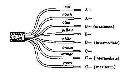
Battery Cable Lead Color Code - Standard RMA Color Code for the wires
comprising the cables used for connecting battery-operated receivers to
batteries. All leads are solid color.
 |
Index
