|
|
|
|
|
|
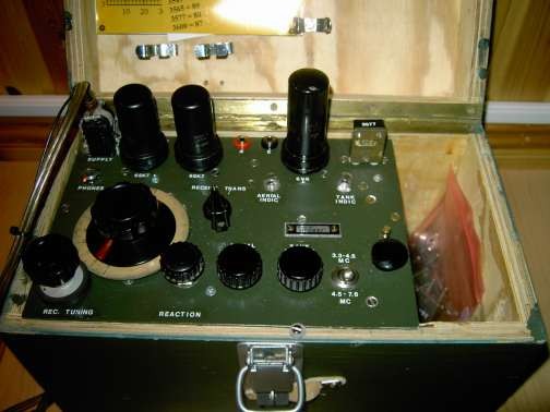
G3VTT ColinThis "Paraset" has been made as another descendent of the original design. The original design had, for amateur radio purposes, poor band spread, switched antenna change over and used valves of lower gain. This version has a built in TR switch using 4 diodes and its coverage is limited to 3.500 to 3.580 which with a single large tuning knob gives a more than required tuning rate. The original 6SK7 valves used as detector and audio have been replaced with 6SJ7's which give improves gain. Overall gain is more than enough and therefore a volume control has been fitted. The set is a joy to use with its full break in and only development work to stabilise the detector supply voltage is required in the future which will keep the receiver on frequency as currently the HT supply changes as the 6V6 oscillator draws extra current on transmit. A more effective power supply is to be constructed. The original design of Paraset was designed for speedy production and easy operation with a strong control station running typically 250 watts to 10 KW as outlined by Pierre Lorraine in his book 'Clandestine Operation'. Although this new approach excludes the constructor from joining another group, the excursion into a newer development is deemed necessary considering the boisterous amateur band conditions we now have. (Anyway no real radio constructor copies a circuit exactly, he uses the parts to hand!)
|
|
|
|
|
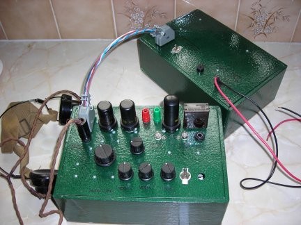
G4VSZ CharlesOne of two "paraset" type set built in 2006 and run from inverter which is as near a copy of the original vibrator circuit as one can get using transistors. Member of SOC No.851 - Second Class Operators' Club since 14th March 2009. |
|
|
|
|
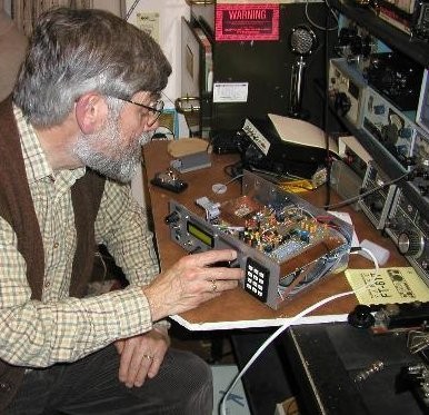
G3RJV GeorgeHonorary member and technical elmer Member of SOC No.213 - Second Class Operators' Club. |
|
|
|
|
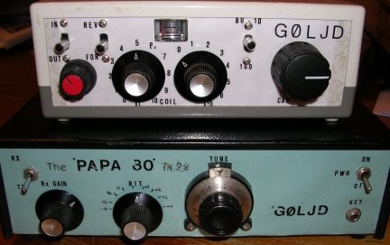
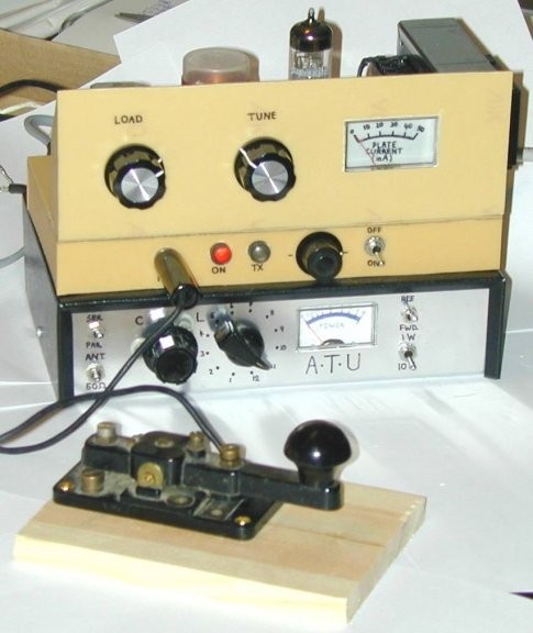
G0LJD BrianFound my 80mtr TX/RX yesterday, also my QRP ATU. Rig is based on a design from Sprat called the Alpha 80. I have added some bits and as the intended use was for holiday use when we were camping I called it the Papa 80 (i.e. /p). It has a VFO which tunes the whole of the 80mtr band (just checked it by listening to tone on main station RX). PA stage is push-pull delivering 1.2 watts into the dummy load. Audio stage via lm386 with added sidetone board. ATU is (I think) a L-match, with multi-tapped coil and old RX capacitor. It also has a built-in SWR meter. Member of SOC No.852 - Second Class Operators' Club since 14th March 2009.
|
|
|
|
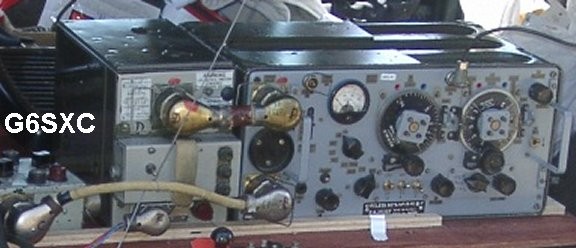 |
G6SXC JohnUsed to run a "19" set on AM phone but enjoyed others using it on CW!! |
|
|
|
 |
G0UPL HansI started fiddling with electronics when aged 5, my Grandfather (lifetime British Rail electrician) gave me a buzzer, a 4.5V battery, flashing bulb and a switch. My Father was a homebrewer too. I messed around with various electronics but did not come to amateur radio until I took my license on leaving university in 1994. My sworn commitment at that time being that I would only ever operate homebrew equipment I'd built myself. Then I got a job and an XYL and life intervened. So it wasn't until 2002 that I built my 1-valve ECL82 CW TX for 80m, putting out about 5W maximum - and my polyphase method direct conversion receiver. My first QSO was on 25'th March 2002 with Larry G4GZG. At that time the forward/reverse power switch on the ATU was labelled upside-down so my report from Larry was 569 at 12 miles DX, with 30 feet of attic wire tuned for worst possible SWR. That problem was soon discovered and rectified and I've now had over 600 QSO's, but still all 100% homebrew, 100% CW, 100% QRP, 100% rockbound and all on 80/40/30m.
|
|
|
|
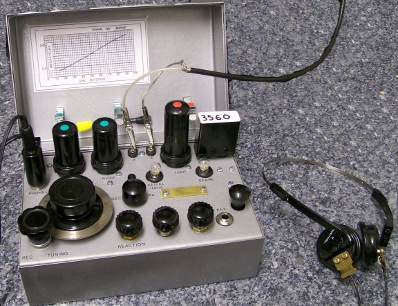 |
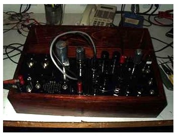
Geoff G3YVFThe paraset is now working on receive. An "original" paraset tunes such a large range that it is hard to tune into a cw signal on a crowded band. So much so that it is as good as pointless trying to use the same tuning range to Rx amateur stations. So my paraset only covers part of the 80m band. This gives a really slow tuning rate and makes it a delight to use. G4VSZ did have a hand in making this as he prepared all the laser cutting drawings which is why the front panel is so exactly like the original to make little difference. In actual fact I do not know where any difference are !!!! Finished TT Paraset.......transistor/transistor version. Uses 6 devices, two of which are fitted inside each valve can. So it looks like the real thing or very close! This TT Paraset will of course work off 12v and draws very little current. For those who look close with zoom they will see it is bandspread making contacts easy on 80 as it only covers 3.5 to 3.6 with a small overlap each end.
|
|
|
|
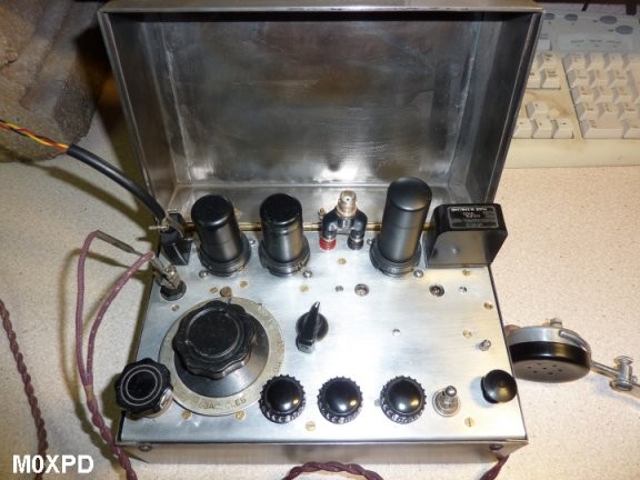 |
Paul M0XPDAnother nice example of a home brew paraset.
|
|
|
|
|
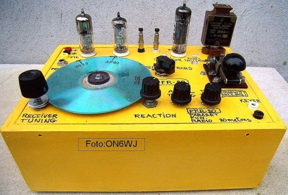
ON6WJ JosMaybe a few words about my PFR-80 ( Paraset Fun Radio for 80 meters) I spent about one year collecting as much as possible "genuine parts" for a "real" replica Paraset, but could not wait to see/hear how this transceiver (or better) this TX/RX would work in the field. Well surprisingly (this is not a winner at all ) but made some nice QSO's with The schematic is the same as the original Paraset , but EL84 instead of the 6V6, EF89 as detector, EF80 as LF amplifier I wanted to use those tiny "polyvarcons" variable capacitors ( 2 x 240 pF ), the same trick using a common broadcast 2x 500 pF variable capacitor for a magnetic loop, no losses between the rotor and stator vanes, the total capacity is halved and the total breakdown voltage is doubled... but would try this first in real world. I wound the same number of windings enamelled copper wire (from original drawings) on a cardboard tube (toilet paper), Xtal, EL84,two "jumbo" LED's ("Tank" & "Antenna" Tuning indicator), a few resistors , capacitors and off we went... After a few CQ calls, made a qso with French Radio amateur station. Until now Dec 2009 contacts have been made with G, GM,F, PA,LA,DL and OE power is about 3,5 Watt output, sensitivity : less then one microvolt for copying signals (of course holding breath and even birds have to be silent for a while but it is a lot of fun. |
|
The KK6XK Paraset ProjectI was looking for a Winter project and first learned about these rigs from the Italian website http://www.qsl.net/ ik0moz/paraset, but soon found out there were a number of resources available on their design and construction, most notably, http://www.paraset.co.uk While we all start out wanting to make something close to original, for my first one, I wanted something completely functional and to be able to use parts I had on hand. And, I had a number of design changes I wanted to try out. Apparently, most people who make one end up making several different versions and once you get the first one to work, the rest come much easier. Click for more information on the KK6XK project |
|
|
|
|
Bertil Bengtsson, SM6AAL Bollebygd
Sweden
Click for another picture |
|
|
|
|
|