| 9th July
2010
The start of the build of a replica
Paraset |
The CAD files were downloaded, from
this web site, as a trial and following the instructions as shown. Downloaded
CAD files were then sent to the laser cutters (Campbells in Chatham) attached
to an email.....and now the metal is being cut..... 1mm bright mild
steel.
NOTE on cad files
Our laser cutting files do not have every
hole included deliberately, when compared to other cutting patterns on the
web. If we put every original hole in you might get stuck for a part that
has to have those hole centres.....since we leave some holes out as you can
soon drill them if needed.
Do you need a flat pack or folded pack
of the metal work?
If you have no access to a laser cutter
and would like a flat pack, or a folded pack then please email directly
at:-
gw.woo@btinternet.com
and he will reply as to the possibility
of supplying such a pack to you. |
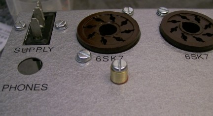
| Paraset knobs Bukgin
Type K94
If you would like to have the chance of
replica knobs for you Paraset
click
here |
If
you have not read the "How our Paraset works" section then please have a
look there as many of your questions will be answered !!
|
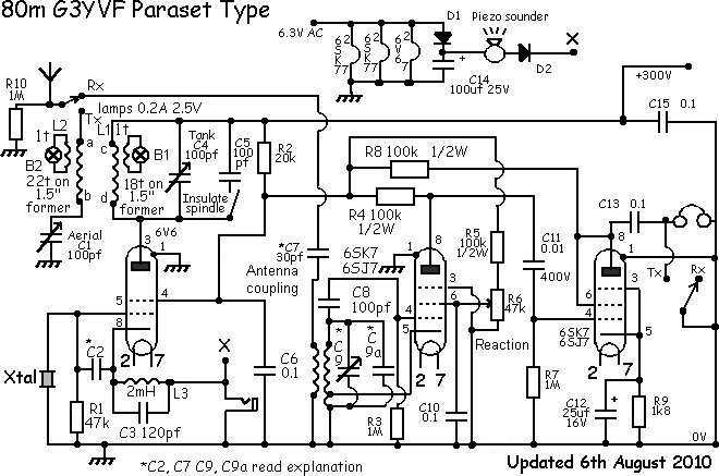
| This is the circuit diagram of the
set as it will be built.
Explanation
for C2 is here
Explanation
for C7 is here
Explanation
for C9 and 9a is here |
 |
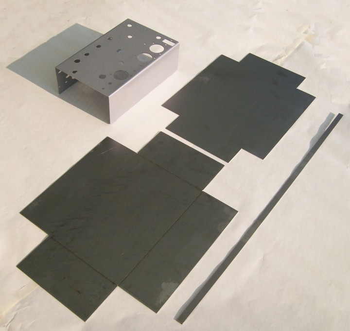
| 12 July 2010
Here is a picture of some of the metal
work as received from the laser cutters and also a chassis that has been
folded. The laser should have marked out the folding lines for you, do not
remove these when you sand the surfaces. If you look at the picture you can
clearly see the folding line as etched by the laser on the bottom part which
forms the box.
At this stage one needs to emery off all
rough edges and all surfaces now whilst they are flat. Use emery cloth (or
sanding paper if that's what you have) to remove all razor sharp corners...don't
"round" them off, just remove the sharp corners so you cannot get cut by
them when performing operations !
Use a file on all those edges to be soldered,
as the laser cut edge will be "blued" slightly making it difficult to solder
later.
I de-grease the parts using hot soapy
water, you might like to use some sort of de-greaser. Leave the parts to
dry. When dry you can proceed to the next stage which is folding the box,
lid, chassis and lip.
|
 |
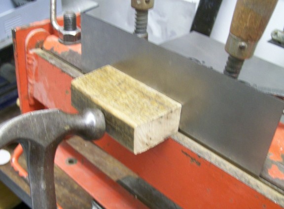
16th July 2010
We like to think that our laser cutting
files do produce a good box if folded with a little care. Don't rush.
You might like to read this before bending
your box.
Here you can see the bending operations
needed to fold the box, lid and chassis. Fold the box using two bits of angle
iron in the vice and a block of wood (very hard wood...oak) and fold the
ends into the sides...just. This will ensure an overlap making a good solder
joint and the chassis will fit into the box nicely.
|
 5 5 |
| Check where to place the etched line
when folding the chassis by offering it to the box first to see exactly where
the fold will "fall"....this will ensure a good fit. Mild steel is soft,
bends easily and is easy to dent with a hammer so use this tool carefully.
You can sand out any marks before painting. Take care with bending and marks
and then there will be less sanding to do. |
 6 6 |
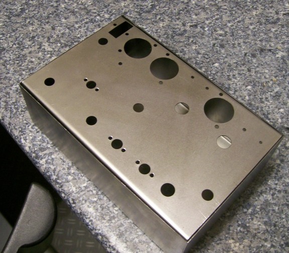
| Look at the photos and you can see
a finished box, chassis and lid.
|
 7 7 |
A pleasing result we think. This leaves
the lip to be bent and fitted and then cut to length but this is only done
after the box and lid are built and soldered at the corners.
|
 8 8 |
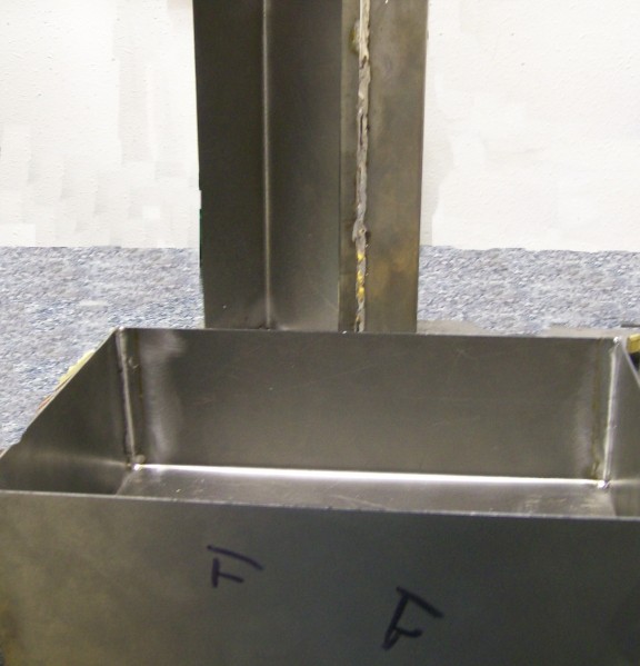
| Soldering
Now drill out the corners with a small
drill (the holes already exist having been cut by the laser) these holes
being there to help bending operations. Drilling them out removes the blue
surface allowing the solder to take.
Make sure each side fits correctly and
stays in position then, If you can, pre heat the metalwork on the gas stove
just a little and using a large soldering iron (60w or more) solder the
corners.
Clean the strap of all blue edges and
sand clean and degrease. Now bend the strap to fit tightly to the edge of
the lid. I know it is too long.....you cut the excess off later.
Tack the lip using solder and check it
fits halfway over the edge of the lid. Then pre heating just lightly if you
can solder along the lip securing it to the lid. Solder a couple of inches
at a time and squeeze the lip tightly to the lid using small pliers.
Trim off the excess and file the edges.
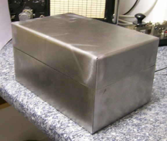
Dress the edges of the box and lid using a file and then sand clean. Here
is a picture of a finished box prior to sanding clean ready to fit a hinge
and then paint. We hope you like it.
|
 9 9 |
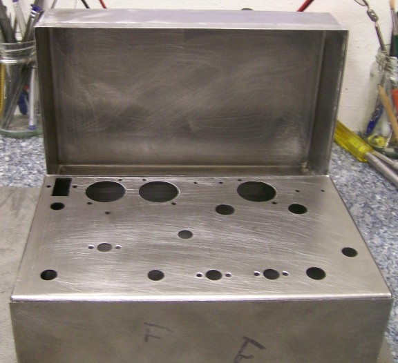
| Now take the chassis and see if fits
into the box. You may need to file one end to make sure it fits snugly into
the box. Once you have done this, sand all surfaces ready to paint now or
after you have fitted the hinge. It is up to you. This photo shows the finished
metal work ready for painting. |
 10 10 |
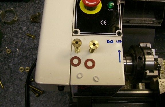
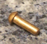
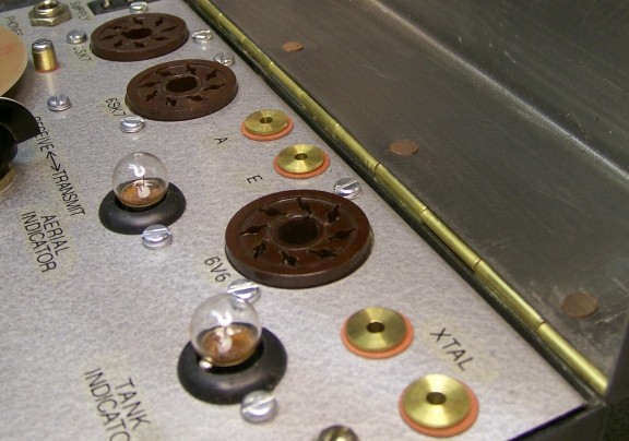
| 17th July 2010
Make your antenna and earth sockets and
crystal sockets from some brass bolts. File the head down until it is flat...or
if you have a lathe use this. Now grip the bolt in the vice and drill down
it with ever increasing size drill until you get to 3mm. Yes sure, the first
one you drill you will come out the side of the bolt! But you will get the
skill required after a couple of attempts and drill the holes correctly.
Of course if you have a lathe......use that.
Incidentally grip the bolts in the vice
using a couple of nuts on the bolts, this way the thread is not damaged by
the vice...or lathe chuck come to that!
In the photo you can see two such sockets,
they are fitted with insulating washers and a small insulating sleeve (made
from the outer of white co-ax cable) which prevents the bolt from shorting
to the chassis. The finished ones look very close to the original type fitted
except for the brass colour!
In the back ground you see some odd bolts
lying around, I used 0 BA sized bolts. You will need four and don't forget
you will need four nuts and four insulating washers and two solder tags to
fit the bolts.
|
 |
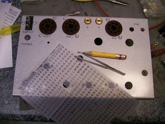
| 18th July 2010
Rub down lettering.
With the preparation done for painting
the front panel it was sprayed with normal crackle finish "Hammerite". After
the paint has dried the lettering can begin.
We use rub down lettering on the Paraset
front panel. As you can see in the picture this lettering can be purchased
from "WHSmiths" or similar shop. It comes under a variety of names such as
"Letteraset" or "Dry Transfer lettering" etc. There is a skill required to
get this to look good when completed. Here are a few pointers....
1 If you have access to a pc, great,
start a new word document and type in each word (capitals please!) and centre
justify each word. Between each word type in the letter "I" twice. Once they
are all typed in and the pc has centralized them you can now see at a glance
where the exact centre of each word is. Now you know this you can place the
lettering in the right place with respect to the controls. |
 |
| 2 Put a line of masking
tape somewhere on the front panel and get it straight and level with respect
to the edges of the panel. Use this as a guide to placing the sheet of lettering
down exactly in line. You might have to use several such lines of masking
tape.
3 If the letters are not in a straight
line, not spaced correctly.....in short anything that makes the wording look
wrong then it is wrong. Take it off, using sticky tape to attract the
letters/word that is at fault and do it again. It will be no good if you
leave it as your eye will always go to the faulty lettering.
4 Varnish over the lettering with
satin or matt polyurethane varnish or similar. Don't touch the panel for
a couple of days allowing the varnish to harden. To damage it now will really
give you a headache to repair it. |
| Insulated dial pointer
To make a change from all that lettering
which can be boring (!) I fitted the insulated dial pointer.
As you know the Paraset has a built in
key...which some folk find hard to use and would like to use an external
key.
I fit an insulated dial pointer ( which
cannot be seen easily ) and connect this to the keying circuit.
Now I can use an external key by connecting
it to this insulated pointer using croc clips the other side of the key going
to the chassis. You like?
If this is for you make and fit it now.
I use fibre washers to insulate the pointer from the chassis.
Have a good close look at the
pictures.
|
 |
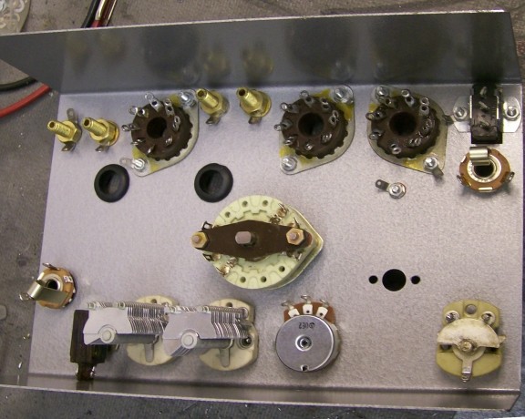
| Adding hardware
Now the matt varnish has dried on the
lettering some of the hardware can be added. You will notice this paraset
has an additional variable capacitor fitted where the slow motion drive would
normally fit. Also a key jack is fitted where the morse key would normally
go. More on these two modifications later...suffice to say this is a bespoke
version the builder wants. Use locking washers on all the nuts/bolts to make
sure they do not come undone. Where this cannot be done use some varnish
on the thread which will lock the nut/bolt thread when it dries.
Look at the photos to give you some idea
of how the parts are fitted. Of course you will need to refer to the building
instructions elsewhere on this web site (click below) when it comes to soldering
in the components.
If
you are sticking to the design shown there.... well follow the instructions
carefully.
|
 |
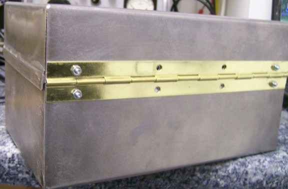
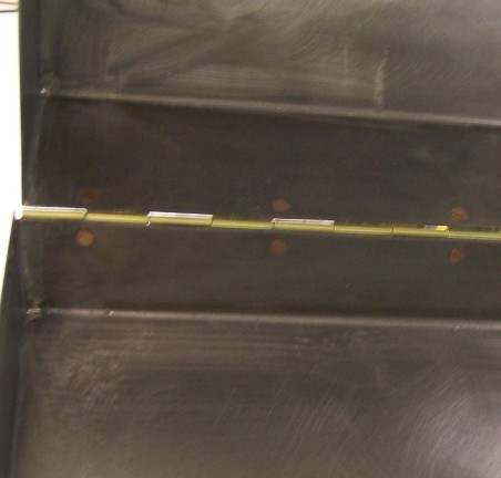
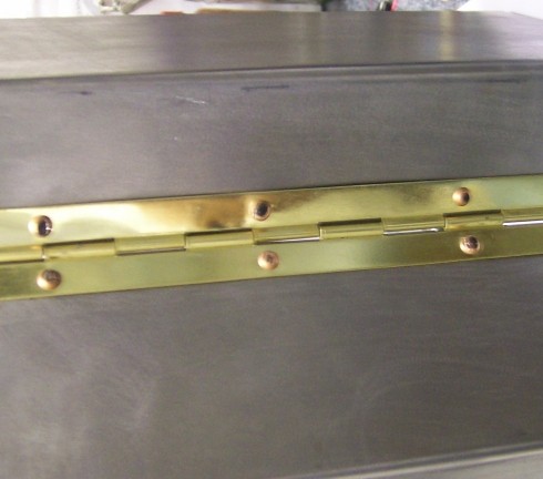
| 19th July 2010
The hinge can be offered up to the cabinet
and placed so the holes are centrally spaced about the centre line of the
box. Mark the hinge for length, mark the hole positions and then cut the
hinge and drill the holes. Remove all swarf. The hinge is best fitted with
small rivets (as the picture shows) or if you cannot get rivets use round
wire nails which can easily be cut to length and used as rivets.
Rivet heads will be flat inside the box
when hammered down...and so they will not foul the chassis as you push it
in the box. You will note the paper sticking out the box.....this is to prevent
the screw heads from damaging the paint on the chassis whilst I try the
"fit".....
 |
 |
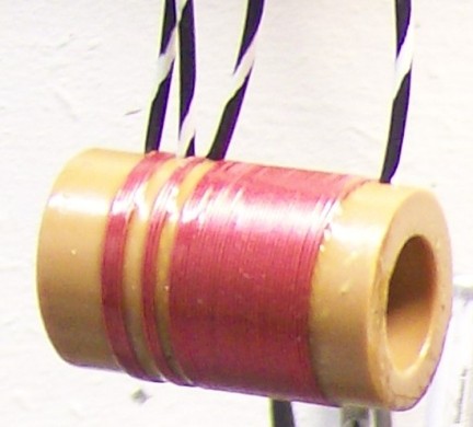
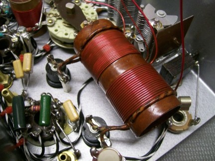
| 20th July 2010
Here you can see the receiver coil hanging
up drying as it has been painted with varnish to fix the windings.
Drill pairs of small holes in the former
to pass the wire through as this will stop the coil from un-winding! Plastic
coil former, close wound turns and this coil is similar to the original.
Note the turns start from left and wind
to right.
As you can see in the picture are from
the left 5 turns and tap, another 3 turns and tap and then 33 turns to the
end.
This produced a coil going from 8 to 3.3
MHz. The high end frequency limit is determined by your circuit's stray capacity
and so it will vary. The low end limit is determined by your tuning capacitor's
maximum capacity.
This is quite normal.
|
 |
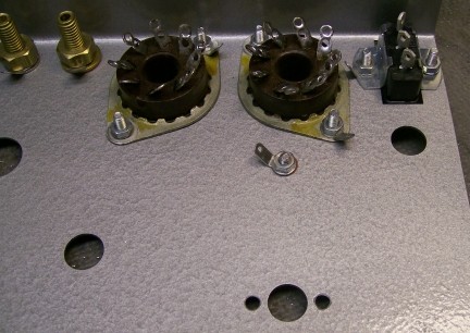
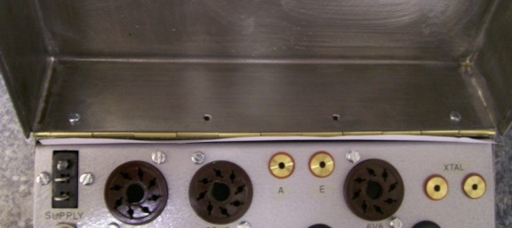
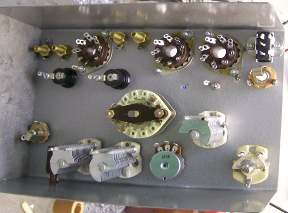
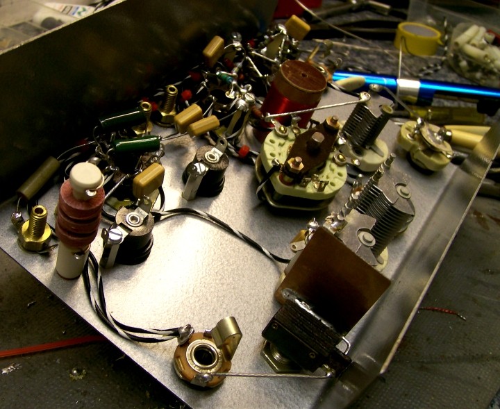
| If you look further most hardware
is fitted to the chassis and soon the wiring will commence.
If
you are going to follow the circuit we use then don't forget to follow the
instructions elsewhere on the web site by clicking on this
link.
|
 |
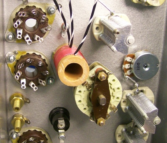
| The wiring up!
The coil fitted here needed just such
a hole drilled. The position of the coil, once establishing it would fit,
in is marked, drilled, swarf removed and the coil fitted. See the photo.
You will also notice that I have started
to fit some of the wires but only the earth connections to the tuning
capacitors....and in very stout wire indeed. We don't want these wires moving
about or the receive frequency might start to wobble!! |
 |
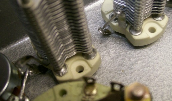
| You can earth the variable capacitor
rotors using a very short stout lead by fitting a solder tag under one of
the mounting of the capacitor with a star washer which enables a good connection
to the chassis to be made. Under the other mounting fit a washer (or may
be two) as without this the capacitor shaft will stick up at a slight angle.
See the picture. |
 |
| Now we come to Wiring
up a replica Valve Paraset" using, where possible, parts as used in the
original. We will explain everything as best we can to make your build enjoyable.
DISCLAIMER
As we have no control over your build,
whilst we are happy to try to answer your questions, responsibility of the
build is yours, as are precautions regarding HIGH VOLTAGES such as
are necessary with valve equipment. If you have any doubt in your ability
to safely construct a Valve Rig, then we humbly suggest you take a look at
the
Transistor
Paraset.
These pages show the order of assembly
of the components


Then also have a look at the pictures
below to have an enhanced idea of what you could achieve. |
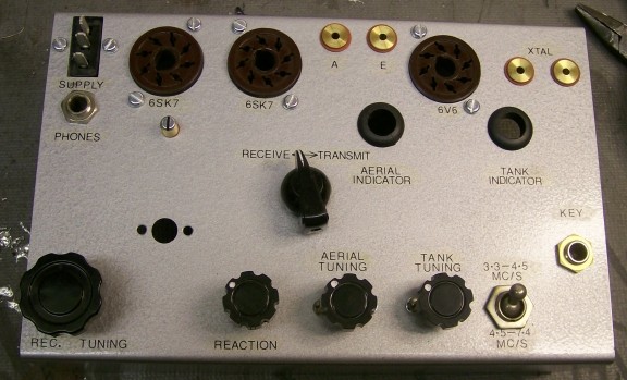
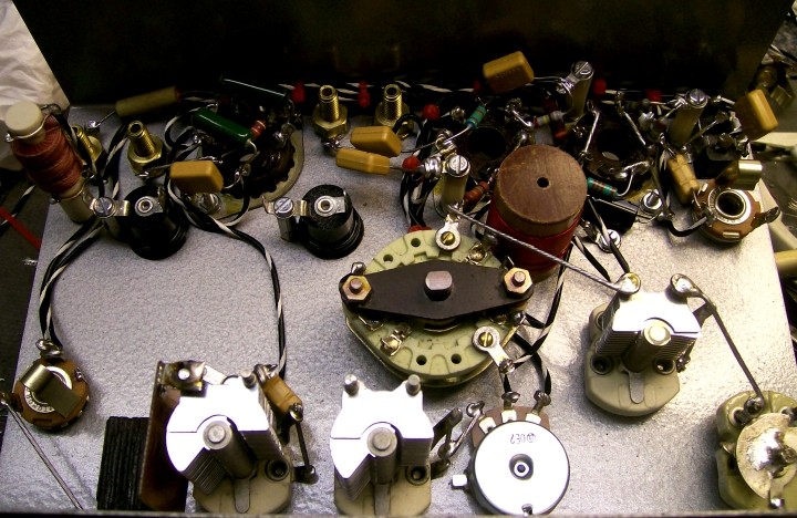
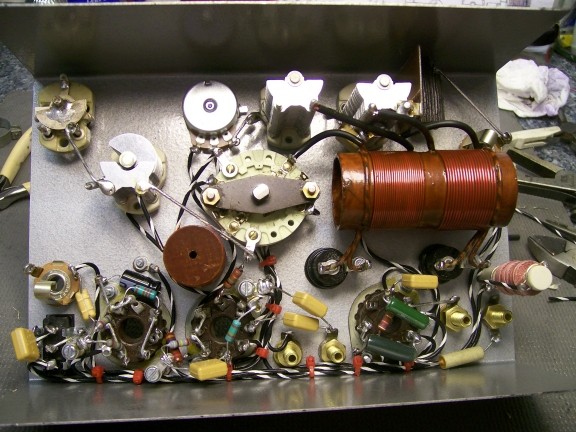
| 23rd July 2010
Here are some photos of the paraset so
far.
A couple of minor changes have been made
to the layout for experimental purposes and you may spot these.
One in particular can be seen easily.
Look for the small copper plate fitted to the tank tuning capacitor. This
is a home made 100pF capacitor, the one that is switched across the tank
to get a lower tuning range on the transmitter. In normal use this capacitor
is "stressed" so a home made one of double sided copper pcb is being tried
here. This should never fail! You will also see I came across a really good
quality R.F.Choke for the PA so I used it!
In some places I used two components in
parallel to get the right value so don't worry if you see too many
components!
|
 |
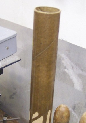
| It is nearly ready for testing.
The tank coil has to be made now when
I can find some tube to make it from.
This coil assembly will probably be made
from the tube that aluminium cooking foil comes on. It will be soaked in
varnish and allowed to dry hard before working on it to make the coil.. |
 |
| Here we are nearly finished. If you
look at the picture you see that it is coming on quite well. The box still
has to be painted and the spring clips fitted for the valves in the lid.
The chart has to be printed so the paraset receiver can be calibrated. This
comes later.
|
 |
| For now I am waiting for polyurethane
varnish to soak in and dry on the cardboard tube that will form the main
pa coil assembly. Look at the picture. It has had a thorough soaking in the
pot of varnish. When wound and varnished again with a deep coloured varnish
it will look a little more realistic!
Paraset knobs Bukgin Type
K94
Look at the top of this page for
more details
|
 |
| Here you can see the rivets have been
bashed home with a hammer.
The picture shows the inside of the box
There is no secret to riveting. However
a couple of pointers might help:
1
Countersink the holes (a drill for this
is perfect) on the inside of the box and lid so that the splayed rivet material
has somewhere to go. This will enable you bash the rivets flush to the surface
which is something you want. Think about it!!
|
 |
| 2
Use copper rivets as they deform easily.
Steel ones do as well so if that is all you can get use them. If all else
fails try using some round wire nails. They too will rivet over if you hit
them with a hammer.
3
Try a practice run of riveting. Rivets
are cheap.......paraset boxes with all that metalworking working involved
are not cheap!
The picture shows the outside of the
box |
 |
| You can now see the chassis fits easily
into the box. All that is left to do now is clean the box, lid and hinge
of all swarf and rough edges and then paint. |
 |
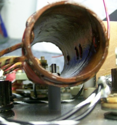
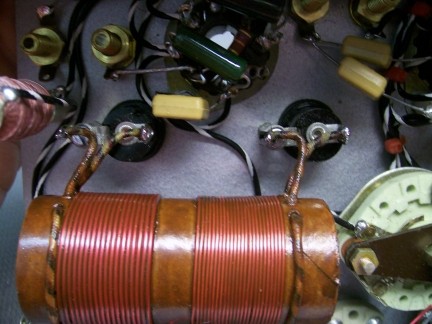
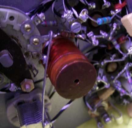
| 24th July 2010
Here you can see the tank coil has been
wound and fitted to the chassis on a small insulating stand off. This allows
one room to fit the coil as space is at a premium. The Tank coil is 18 turns
of large wire if you have it (as per original....but this is not critical)
if not use what you have available. The Antenna coil is 22 turns of slightly
smaller wire....again this is not critical but looks more the part...but
other wise use what you have available.
Drill the mounting hole in the tank former
after you have wound the coils. Once wound and varnished several times offer
the coil up to the chassis and then making sure it fits in mark and drill
the mounting hole in the chassis front panel DON'T SCRATCH THE PAINT!
Secure the coil, and then varnish the
nut and bolt so they cannot inadvertently come un-done. Actually I varnish
all my nuts and bolts at the end to finish off. makes a nice job.
|
 |
Look at the photos for guidance.
|
 |
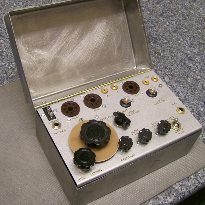
| Valves should be in the post but here
it is ready for testing and then receiver calibration once it is in its'
box. It must be calibrated when in the box as removing it will cause a shift
in frequency. This is to be expected and not a fault. I am waiting for the
correct knobs (see paraset "knobs" on this site) and a dial to appear!! I
haven't got that yet but I will find one.
|
 |
| Whilst waiting for the valves I have
spraying the box bit by bit so in the next couple of days it all should be
ready to "FIRE IT UP" for the first time. |
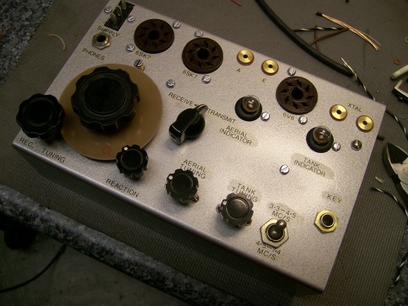 |
| 25th July 2010
Now you can see the painted "cash box"
paraset completed. It needs a dial, which as yet I do not have but live in
hope of finding one. The valves are coming in the post. When the valves arrive
I shall fit the spring clips to hold them in the lid properly. It will then
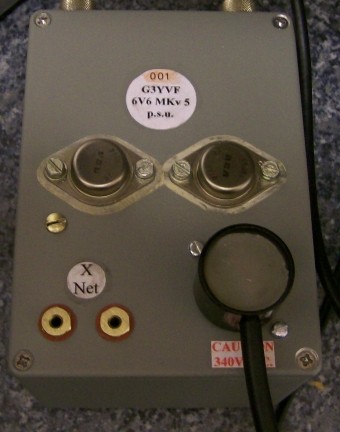
be possible to test this replica paraset. I already have the power supply
working from 12V D.C. using the circuit from this web site, ready and
waiting.
Click
here for link to power supply
You can see by looking at the dates put
on by the web-master how long it has taken. The metal work for the complete
box and chassis were laser cut from files downloaded from this web-site.
Now you can see for yourself the standard of replica paraset that can be
built, using our laser cut files in only a few days. The pictures show the
paraset and below its 12V D.C. power supply.
Have a go yourself and if stuck for
metal work we might be able to help...look elsewhere on this site. Certainly
if you have a problem...send it to us by email and we will endeavour to reply
with some suggestions to put it right. |
 |
| Remember, this web-site is run
in the hope that you build yourself a very good, usable transmitter/receiver
that can hold its' own on todays bands. It has got work, and well. The circuit
that we use (is on this web site) has just a couple of minor changes from
the original arrangement but leads to a transmitter/receiver that will really
earn its' keep. I can't wait to try this one.
When it is tested, details will be
put here to finish the diary of the building of a replica paraset.
|
 |
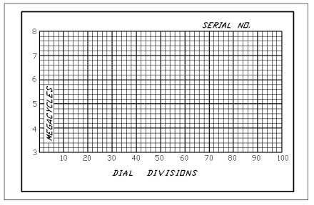
| The calibration chart
This is the chart for inside the lid which
is as near an original as we can get !!!
Overall dimensions are 108mm long by
70.5mm wide.
To use the graphic
-
Right Click on it and
-
use "SAVE as ..", and
-
save it in the usual way.
When the file is opened in say "Paint
Shop Pro" you can check the size, adjust as needed, colour it if you like
(HTML colour code #F7CB55 looks nice) and then print it off! |
 |
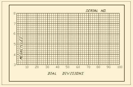
| This chart is coloured as indicated
above and does give a nicer look than plain white !!! |
 |
| On the front of the Paraset there
was an identification serial number.
This appears to be an aluminium stamping
with the number added after the stamping. The recess is painted black and
it is held in place with rivets probably also aluminium.
The type style is apparently Gill Sans
MT which has also been used in this section. |
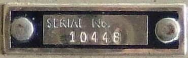
The length of the part we estimate at
38mm and width 11.5mm |
| The valves arrived, 6137's which are
6SK7's by another name. These were plugged in along with the 6V6 and the
paraset put on test.
The receiver did not work too well, the
reaction was very fierce. The problem was caused by me missing out the resistor
in series with the reaction pot. Once I fitted the resistor the reaction
was working well. The receiver coverage was slightly too low in that it tuned
from 7.1 to 3.2MHz. This was cured by removing two turns from the top of
the receiver coil. This was carried out with the coil in-situ and the top
of the winding re-varnished. |
 |
| This allowed the receiver
to cover 7.4 to 3.4MHz....quite good enough. The gain seemed a little low
and this was cured by increasing the antenna coupling capacitor from 82pF
to 120pF. My antenna coupling coil is a small distance away from the main
winding deliberately to reduce the coupling as the normal paraset is easily
overloaded by stronger signals. So 120pF fitted here came as no surprise.
The receiver is working well. The photo shows the top of the receiver coil
where I took two turns off.
The transmitter did not work at all.
Why.....I forgot to connect the anode of the 6V6 to the tank coil. It still
didn't work. I had fitted an 82pF across the cathode rf choke (it was the
one I came across first in the junk box) but it turned out this was just
a little too small in value and was replaced by a 120pF and all is well with
the transmitter now. |
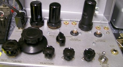
| The dial as yet to materialize but
when it does I shall be able to calibrate the receiver...in the mean time
I can short wave listen! |
 |
| 17th August 2010
The dial arrived at last thanks to a
kind offer and so now the paraset has been calibrated.
It was my original intention to try and
use the paraset with its normal receive coverage of roughly 3.3 to 7.4MHz.
But like this the receiver does not give of it best as the L to C ratio of
the receiver tuned circuit is optimized for best performance. Remember I
want to use this little rig and have lots of contacts. The receiver
MUST hold its own on a ham band. Having listened to it there was only
going to be one outcome. It had to be band-spread on 80m and the L to C ratio
of the coil needed to be changed. |
 |
| I rewound the coil so that approx
half the turns were needed on the main winding. Then by trial and error (
I used a trimmer) I found that value of fixed capacity which allowed the
paraset to tune just above 3.6MHz when the tuning capacitor was unmeshed.
Then I gradually meshed the tuning capacitor until just below 3.5MHz was
reached. Looking at the tuning capacitor it was clear that quite few vanes
would need to be removed....so one at a time I took them off and re-checked
the tuning range. In this way I gradually spread the cw portion of 80 across
the dial. |
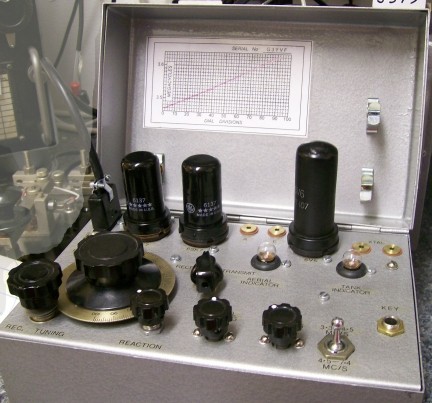 |
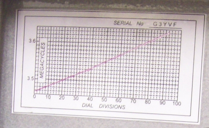
| If you look at the photo
and study the chart you can see my paraset tunes from 3.47 to 3.64 very nicely.
With this amount of fixed capacity (approx 240pF) the receiver is wonderfully
stable and the reactions slides in and out with barely a change in frequency.
I HAVE MADE IT ! And doesn't it go well on receive.
If
you are patient enough and follow the instructions you can achieve results
like the picture indicates. A nice straight line tuning characteristic. If
you think this is good...then wait till you try the receiver as the change
in LC ratio to achieve this tuning characteristic makes the reaction easier
to use.
To test the transmitter I short out the
antenna socket to the earth one and key the transmitter. Both bulbs should
light up well if all is ok. All I need now are the correct knobs for the
controls and my paraset a Whaddon MkVII/2 is finished! Well what are you
waiting for!!
|
|
|
|
|


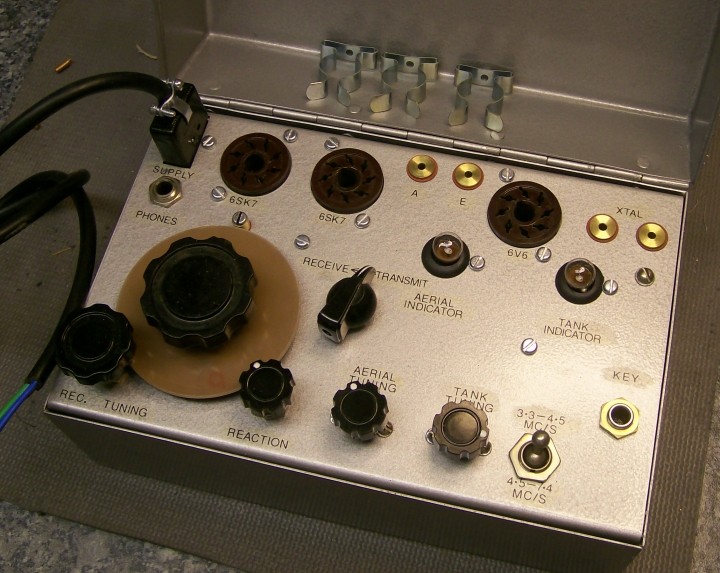
 Nearly completed !!!